SOFTWARE EXAMPLE IN QUICKBASIC
10 CLS:KEY OFF
20 BYTE = &H3FC: 'COM 1 Set Com Port NOTE: Remove the apostrophe after the line number
30 'BYTE = &H2FC: 'COM 2 to enable the COM Port or add the apostrophe to
40 'BYTE = &H3EC: 'COM 3 disable the COM Port.
50 'BYTE = &H2EC: 'COM 4
60 PRINT" AR-2 RELAY INTERFACE TEST COM 1"
70 PRINT:PRINT"(1) De-energize relay #1"
80 PRINT"(2) Energize relay #1"
90 PRINT"(3) De-energize relay #2"
100 PRINT"(4) Energize relay #2"
110 PRINT "(5) Exit program"
120 PRINT:PRINT"Press key to test relay"
130 K$=INKEY$:IF K$="" THEN 130 :'Check for key pressed
140 IF K$="5" THEN CLS: END :' Exit program
150 A=VAL(K$) :' Convert string to a number
160 IF A<1 OR A>4 THEN 130
170 GOSUB 190 :'Go to subroutine to control relays
180 GOTO 130 :'Return to loop
190 X=INP (BYTE) :'Read modem control register
200 IF A=1 THEN X=X AND (NOT 2) :'Set bit 1 to zero
210 IF A=2 THEN X=X OR 2 :'Set bit 1 to one
220 IF A=3 THEN X=X AND (NOT 1) :'Set bit 0 to zero
230 IF A=4 THEN X=X OR 1 :'Set bit 0 to one
240 OUT BYTE,X :'Write to modem control register (set relays)
250 RETURN
MODEM CONTROL REGISTER I/O PORTS
COM 1 3FC (hex)
COM 2 2FC
COM 3 3EC
COM 4 2EC
Page 5
TROUBLESHOOTING
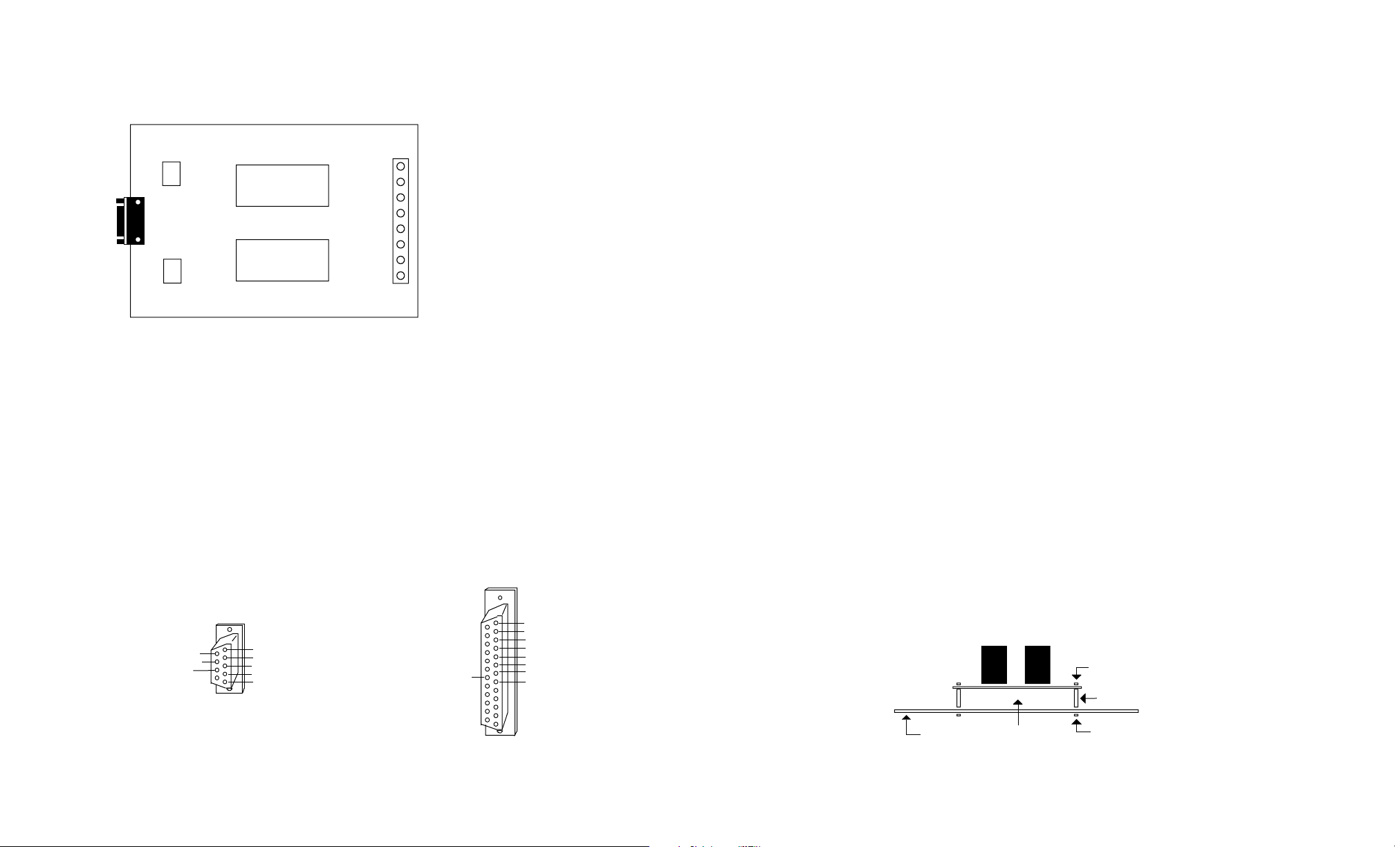
(1) Check for correct power and polarity to your AR-2 by using a multimeter to check the voltage at the AR-2
power terminals (the 2 small terminals on the lower right side of the AR-2, with the terminal block on the bottom).
Voltage should be between 9 volts and 14 volts DC and the polarity should have the negative on the far right terminal
(marked on the underside of the AR-2).
(2) Check your cable to the AR-2. The cable used to connect the AR-2 to a 9 pin RS-232 com port is the CC-
DE9SAR2 which is a direct pin to pin cable. Pins 4, 5 and 7 must be connected through the cable from the DB9 male
to the DB9 female connectors. You may use a multimeter set to ohms to check for continuity. The cable used to
connect the AR-2 to a USB port is the CO-USB cable. When using this cable, it may be necessary to remove the 2
connector nuts on each side of the AR-2 DB9 to plug in the CO-USB. It is also necessary to install the USB cable
driver (provided with the CO-USB).
(3) Run the Test Program supplied on CD with your AR-2. Install the AR-2 Test Program on your computer. The
universal App will run on all Windows computers (follow installations in the readme file). The .Net App will run on
Windows XP (service pack 3), Windows Vista, Windows 7, 8 and 8.1. When the test program is first started, enter the
com port that your AR-2 is connected to. When the program starts, test the relays. The test program will not start if it
is unable to find the com port entered. If the program will not start or if the relays do not operate, go to the next step.
(4) Check the Com Port used with the AR-2. Open device manager by clicking on the "Open Device Manager"
button on your installation CD (or by going to control panel). Click the small triangle (or +) to the left of Ports to
expand the Ports category, right click on the Com port that you have the AR-2 connected to and click properties.
Check the Com port status and verify that you have the test program set to this Com port and verify that you have the
AR-2 connected to this Com port.
If you are connecting the AR-2 to a USB port, the Com port entry must be "Prolific USB to Serial Comm Port". Right
click on this entry, click properties and open the Driver tab. Your USB Com driver must be Prolific version 3.4.62.293
or higher (dated 10/17/2013 or later). If your USB Com driver is not up to date, then right click the "Prolific USB to
Serial Comm Port" entry and click update driver. If you do not see a "Prolific USB to Serial Comm Port" entry then the
USB cable driver is not correctly installed. You may re-install the driver from the supplied CD or Windows Update. You
may verify that you have the AR-2 connected to this "Prolific USB to Serial Comm Port" entry by watching the entry
and unplugging the AR-2 USB cable from your computer. The entry should disappear and then re-appear when you
re-connect the USB cable to the AR-2.
Please contact EECI Support at (800) 842-7714 or (937) 349-6000 if you require additional assistance or have
questions.
CONTROL SOFTWARE
The relays on the AR-2 are controlled with RTS and DTR which are RS-232 control lines and are primarily used for
controlling a modem (RTS=request to send and DTR=data terminal ready). The number 1 relay is energized by
placing RTS high by setting bit 1 in the modem control register. The number 2 relay is energized by placing DTR high
by setting bit 0 in the modem control register. Software examples in G W Basic, QuickBasic, Visual Basic, Turbo C,
C#, Microsoft ASP and others are provided on the disk supplied with your order. The AR-2 may be used with any RS-
232 COM port on your PC (provided that you know the correct I/O port for the modem control register). Standard
modem control register I/O ports for COM 1 through COM 4 are shown in the Basic program on page 4.
NOTE: The AR-1 uses only the RTS control line (DTR is not used). The AR-1 may be ordered with the control line set
to DTR if required. You may also change the AR-1 setting by breaking the circuit track and manually soldering the
jumper to DTR (contact EECI support for assistance).
Page 4