
Edco EDG-7 Hoja de datos

Printed in USA
©2001
Page 1
E-EDG7-PL-1201
100 Thomas Johnson Drive, Frederick, MD 21702-4600 USA
Phone (301) 663-1600 • 1-800-638-3326
Fax (301) 663-1607 • 1-800-447-3326
PARTS LIST MANUAL
MODEL EDG-7
EDGE GRINDER
PART NO. 56300
REVISED STARTING SERIAL # 1094

Printed in USA
©2001
Page 2
E-EDG7-PL-1201
100 Thomas Johnson Drive, Frederick, MD 21702-4600 USA
Phone (301) 663-1600 • 1-800-638-3326
Fax (301) 663-1607 • 1-800-447-3326
READ AND UNDERSTAND THE OPERATORS INSTRUCTION MANUAL THOROUGHLY BEFORE ATTEMPTING
TO OPERATE THIS EQUIPMENT. Death or serious injury could occur if this machine is used improperly.
SAFETY
MESSAGES
The safety instructions are proceeded by a graphic alert message of
DANGER, WARNING, or CAUTION.
Indicates an imminent hazard which, if not avoided,
will result in death or serious injury.
Indicates an imminent hazard which, if not avoided,
will result in death or serious injury.
Indicates hazards which, if not avoided, could result
in serious injury and or damage to the equipment.
GASOLINE
Powered Equipment
• Do not operate gasoline powered equipment without adequate ven-
tilation. Carbon monoxide is an invisible, odorless gas that can kill.
ELECTRICAL
Powered Equipment
•ELECTRICAL HAZARD - Be sure equipment is properly grounded.
Failure to comply could kill or result in serious injury.
The engine exhaust from this product contains chemicals known to
the State of California to cause cancer, birth defects or other reproduc-
tive harm.
!!
!!
!
GENERAL INSTRUCTIONS
• You must read and understand the operators instruction manual and
all other manuals associated with this machine. For your safety
and the safety of others around you, it is extremely important to fully
understand how to operate this machine in the way it was intended.
Different model machines or older/newer versions of the same model
may have different parts and controls that you need to understand.
If instructions are not readable or available DO NOT USE this
machine and contact the factory for a replacement Manual.
• You must be able to physically handle the bulk weight and power of
this machine. If not properly controlled this machine can cause
death or serious injury.
• Do not operate this machine in an impaired mental state. You must
be able to exercise good judgement and reactions to maintain a safe
working environment.
• This is a “one person” machine which means only one operator can
be operating the machine at any one time. For the safety of others,
maintain a safe operating distance to other personnel. Your work
area should be defined and appropriately marked so bystanders
and coworkers do not stand or walk near this machine and end up
seriously injured by flying debris or exposing them to harmful noise
or dust.
• This equipment is for Commercial use. Although this is a “one
person” machine your work team should understand how to shut
this machine off and quickly get medical help if an accident strikes
the operator.
• Keep all guards in place during operation. The guards are to pro-
vide protection from inadvertent contact with dangerous moving
parts, pinch points, or hot surfaces.
• Wear appropriate Personal Protective Equipment (PPE) including
safety glasses, safety boots, work gloves, respiratory protection,
!!
!!
!
hearing protection, and head protection. Do not wear loose clothing
that can get tangled in moving parts. Failure to do so could result in
dismemberment or death. Wear an approved respirator when re-
moving hazardous materials or when grinding/cutting dry materials.
Some dust particles such as concrete dust can contain silicate
particles which can cause silicosis (a very serious lung disease).
Contact NIOSH or OSHA for further details. When wet grinding/
cutting, avoid contact with the concrete/asphalt slurry which can
cause serious skin irritations.
• You must maintain this machine per the maintenance schedule in
the operator manual. Remember before adjusting, servicing, or
fueling this machine, disconnect the source of power to the machine
by disconnecting the spark plug (Gas models), or by unplugging the
electrical power cord (electric models) or air hose (Pneumatic
models) AT THE MACHINE so you can assure yourself it remains
unplugged while you are working on it. Do not modify this machine.
Use only genuine EDCO parts and accessories. Repairs and ser-
vice should be performed by approved EDCO dealers or authorized
technicians.
• You should look carefully around the area before you begin work so
you can identify potential hazards such as deck inserts, pipes,
columns, openings, electrical cords or outlets, or any other objects
protruding from the slab surface.
• This machine has no brain so you must use your own. There is no
substitute for safety. The safety decals on the machine are to serve
as a reminder for information you must already know before you
begin using this machine. Take a moment to reread the safety
decals each time you use the machine. If your machine is missing
any decals, contact the factory for a replacement (EDCO 1-800-
638-3326).

Printed in USA
©2001
Page 3
E-EDG7-PL-1201
100 Thomas Johnson Drive, Frederick, MD 21702-4600 USA
Phone (301) 663-1600 • 1-800-638-3326
Fax (301) 663-1607 • 1-800-447-3326
MODEL EDG-7
Date of Purchase
______________________
Name of Machine
__________________
Model # ______________________________
Serial # ______________________________
Belt Size(s) ___________________________
FILL IN INFORMATION BELOW
Toll Free: 1-800-638-3326
FAX: 1-800-447-3326
email: [email protected]
www.edcoinc.com
To insure product safety and reliability, always
use genuine EDCO replacement parts when making
repairs to the equipment.
When calling for parts, specify the MODEL
and SERIAL NUMBER of the machine which can be
found on the NAME PLATE. Keep that information in
the space provided. In addition to this information,
give part number, description and quantity as listed
on the parts list to your parts representative.
Please note: Due to improvements and
changes in the equipment, the illustrations shown may
be different than the actual machine.
HOW TO ORDER REPLACEMENT PARTS
Section Page Number
Safety Messages / General Instructions . . . . . . . . . . . . . . . . . . . . . . . . . . . . . . . . 2
How To Order Repair Parts . . . . . . . . . . . . . . . . . . . . . . . . . . . . . . . . . . . . . . . . . . 3
Illustration 1: Main Assembly Grouping . . . . . . . . . . . . . . . . . . . . . . . . . . . . . . . . . 4
Parts Listing - Illustration 1: Main Assembly Grouping . . . . . . . . . . . . . . . . . . . . . 5
Illustration 2: Motor Grouping . . . . . . . . . . . . . . . . . . . . . . . . . . . . . . . . . . . . . . . . . 6
Parts Listing - Illustration 2: Motor Grouping . . . . . . . . . . . . . . . . . . . . . . . . . . . . . 7
Illustration 3: Water Mist System . . . . . . . . . . . . . . . . . . . . . . . . . . . . . . . . . . . . . . 8
Parts Listing - Illustration 3: Water Mist System . . . . . . . . . . . . . . . . . . . . . . . . . . 9
Wiring Diagram - Low Voltage . . . . . . . . . . . . . . . . . . . . . . . . . . . . . . . . . . . . . . . . 10
Wiring Diagram - High Voltage . . . . . . . . . . . . . . . . . . . . . . . . . . . . . . . . . . . . . . . 11
Limited Equipment Warranty . . . . . . . . . . . . . . . . . . . . . . . . . . . . . . . . . . . . . . . . . back cover

Printed in USA
©2001
Page 4
E-EDG7-PL-1201
100 Thomas Johnson Drive, Frederick, MD 21702-4600 USA
Phone (301) 663-1600 • 1-800-638-3326
Fax (301) 663-1607 • 1-800-447-3326
ILLUSTRATION # 1 - MAIN ASSEMBLY GROUPING
NOTE:
The Head Assembly (Item 14)
changed in Sept. 2003 to the Flexible
Style starting with Serial # 1244.
Click here for the new Breakdown.
The Rigid Style Assembly shown here
is Optional. Order Part # 72004A for
this Style Head Assy.

Printed in USA
©2001
Page 5
E-EDG7-PL-1201
100 Thomas Johnson Drive, Frederick, MD 21702-4600 USA
Phone (301) 663-1600 • 1-800-638-3326
Fax (301) 663-1607 • 1-800-447-3326
PARTS LISTING - ILLUSTRATION # 1: MAIN ASSEMBLY GROUPING
ITEM # PART # DESCRIPTION QTY.
1 72001 MAIN FRAME 1
2 72002 HANDLE BAR 1
3 10055 SCREW, CAP 3/8-16 x 1 2
4 10811 WASHER, LOCK 3/8 2
5 10025 WASHER, FLAT 3/8 2
6 79013 WHEEL 8 x 2-1/2 x 3/4” BRG. 2
7 10428 COLLAR, LOCKING 3/4” ID 2
8 65022 PLUG, HOLE 2” 1
9 77009 BEARING, BALL 3/4” 4-HOLE FLANGE 2
10 10309 SCREW, CAP 3/8-24 x 1-1/4 8
11 10152 NUT, HEX NYLON LOCK 3/8-24 8
12 72009 COVER, DISC 1
13 10016 KEY 3/16 SQ. x 1-1/2 1
14 72004A DIAMOND HEAD SUBASSEMBLY (ITEMS 15-21) 1
15 72004 DIAMOND HEAD FLANGE & SHAFT 1
16 72005 DIAMOND DISC MOUNTING FLANGE 1
17 10049 PIN, ROLL 1/4 x 1 1
18 72007 MOUNT, CENTER BONDED (CB-1120) 3
19 72006 WASHER, CENTER BONDED MOUNT 3
20 10811 WASHER, LOCK 3/8 3
21 10309 SCREW, CAP 3/8-24 x 1-1/4 3
22 72030 7EDCW DIAMOND CUP WHEEL 7” 1
23 72021 NUT, FLANGE 5/8-11 1

Printed in USA
©2001
Page 6
E-EDG7-PL-1201
100 Thomas Johnson Drive, Frederick, MD 21702-4600 USA
Phone (301) 663-1600 • 1-800-638-3326
Fax (301) 663-1607 • 1-800-447-3326
ILLUSTRATION # 2 - MOTOR GROUPING

Printed in USA
©2001
Page 7
E-EDG7-PL-1201
100 Thomas Johnson Drive, Frederick, MD 21702-4600 USA
Phone (301) 663-1600 • 1-800-638-3326
Fax (301) 663-1607 • 1-800-447-3326
1 72013 SWITCH & WIRE HARNESS ASSEMBLY ( 2-13 ) 1
2 40041 PLUG CONNECTOR, LOCKING 20A/125V 1
3 40042 PLUG, LOCKING 20A/125V 1
4 77026 WIRE HARNESS 12/3 x 18” LOA 1
5 41130 STRAIN RELIEF 1/2 NPT x .550 -.650” 3
6 77027 SWITCH w/ ENCLOSURE DP 30A 120-277V 1
7 72011 BRACKET, SWITCH BOX 1
8 10315 SCREW, CAP 1/4-20 x 1-1/2 2
9 10150 NUT, HEX NYLON LOCK 1/4-20 2
10 10365 BOLT, CARRIAGE 10-24 x 1/2 2
11 10831 WASHER, LOCK, INT. TOOTH # 10 2
12 10463 NUT 10-24 2
13 72014 WIRE HARNESS 12/3 x 32” LOA 1
14 10982 TIE, CABLE, BLACK NYLON 11-1/4 2
15 16037 MOTOR, LEESON 2HP-1PH 60Hz 1740 RPM 1
16 10806 SCREW, CAP 5/16-18 x 1 4
17 10213 WASHER, FLAT 5/16 4
18 10801 WASHER, LOCK 5/16 4
19 10054 NUT 5/16-18 4
20 72003 COVER, BELT 1
21 65022 PLUG, HOLE 2” 1
22 10907 SCREW, CAP 3/8-16 x 3/4 4
23 10811 WASHER, LOCK 3/8 4
24 10025 WASHER, FLAT 3/8 2
25 72015 MOUNT BRACKET, BELT COVER 1
26 72012 SHEAVE 4” OD x 1Gr.B x 7/8” BORE 1
27 72010 SHEAVE 4” OD x 1Gr.B x 3/4” BORE 1
28 10278 BELT BX-34 COG 1
29 51226 PULLEY, IDLER 3.125” x 3/4” FLAT x 3/8” BORE 1
30 10908 BOLT, CARRIAGE 3/8-16 x 2-1/2 1
31 10040 WASHER, GARRETT 1”OD x 17/32” ID x .054 THK. 1
32 10025 WASHER, FLAT 3/8 2
33 10011 SPACER, STEEL 5/8” OD x 3/8” ID x 3/8” 2
34 10811 WASHER, LOCK 3/8 1
35 10404 NUT 3/8-16 1
PARTS LISTING - ILLUSTRATION # 2: MOTOR GROUPING
ITEM # PART # DESCRIPTION QTY.

Printed in USA
©2001
Page 8
E-EDG7-PL-1201
100 Thomas Johnson Drive, Frederick, MD 21702-4600 USA
Phone (301) 663-1600 • 1-800-638-3326
Fax (301) 663-1607 • 1-800-447-3326
ILLUSTRATION # 3: WATER MIST SYSTEM
KIT PART NO. 72060
(OPTIONAL)

Printed in USA
©2001
Page 9
E-EDG7-PL-1201
100 Thomas Johnson Drive, Frederick, MD 21702-4600 USA
Phone (301) 663-1600 • 1-800-638-3326
Fax (301) 663-1607 • 1-800-447-3326
PARTS LISTING - ILLUSTRATION # 3: WATER MIST SYSTEM
ITEM # PART # DESCRIPTION QTY.
1 72062 ATTACHMENT, WATER NOZZLE 1
2 10834 SCREW, CAP 1/4-20 x 1/2 1
3 11563 NOZZLE, SPRAY 1/8 MPT (H1/8VV250I) 1
4 11562 BARB ELBOW 90°, 3/8 HOSE x 1/8 MPT 1
5 50069 CLAMP, HOSE, SIZE M6, ADJ. TO 13/16 2
6 72063 HOSE, WATER 3/8” ID x 25” L 1
7 50075 BARB, 3/8 HOSE x 1/4 MPT 1
8 10711 VALVE, BALL 1/2 FPT 1
9 80021 CONN., SWIVEL FEMALE 3/4 HOSE x 1/2 MPT 1
10 72061 BRACKET, WATER VALVE, EDG-7 1
11 10018 SCREW, CAP 1/4-20 x 3/4 2
12 10602 WASHER, FLAT 1/4 2
13 10038 WASHER, LOCK 1/4 2
14 10013 NUT 1/4-20 2
15 11565 CLAMP, LOOM, 5/8’ (SAE SIZE 10) 1
16 10877 SCREW, SELF-TAP HEX WASHER 10-24 x 1/2 1
Printed in USA
©2001
Page 10
E-EDG7-PL-1201
100 Thomas Johnson Drive, Frederick, MD 21702-4600 USA
Phone (301) 663-1600 • 1-800-638-3326
Fax (301) 663-1607 • 1-800-447-3326
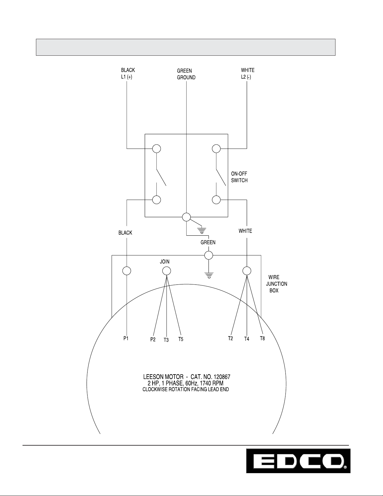
ILLUSTRATION # 4: LOW VOLTAGE WIRING DIAGRAM
Este manual sirve para los siguientes modelos
1
Tabla de contenidos
Otros manuales de Amoladora de Edco

Edco
Edco SECNG-1.5L Manual de usuario

Edco
Edco MAGNA-TRAP TMC-7 Instrucciones de montaje

Edco
Edco 2-EC Manual de usuario

Edco
Edco TG-10 Instrucciones de montaje

Edco
Edco TG-10 Instrucciones de montaje

Edco
Edco SEC-HD Manual de usuario

Edco
Edco Magna-Trap 2D-HDG Instrucciones de montaje

Edco
Edco MAGNA-TRAP TMC-7 Instrucciones de montaje

Edco
Edco MAGNA-TRAP 2EC-NG-1.5 Manual de usuario

Edco
Edco TG-10 Instrucciones de montaje


