SETTING THE INDUSTRY STANDARD
Edbro plc
Nelson Street, Bolton BL3 2JJ, UK
Tel: +44 (0) 120 4528888 Fax: +44 (0) 120 4531957
Spares fax: +44 (0) 120 4393561
Web: www.edbro.com
Technical specificaons are subject to change without noce.
Rev1, July 2011
General Installaon Guide for PTO’s PTO 01-01
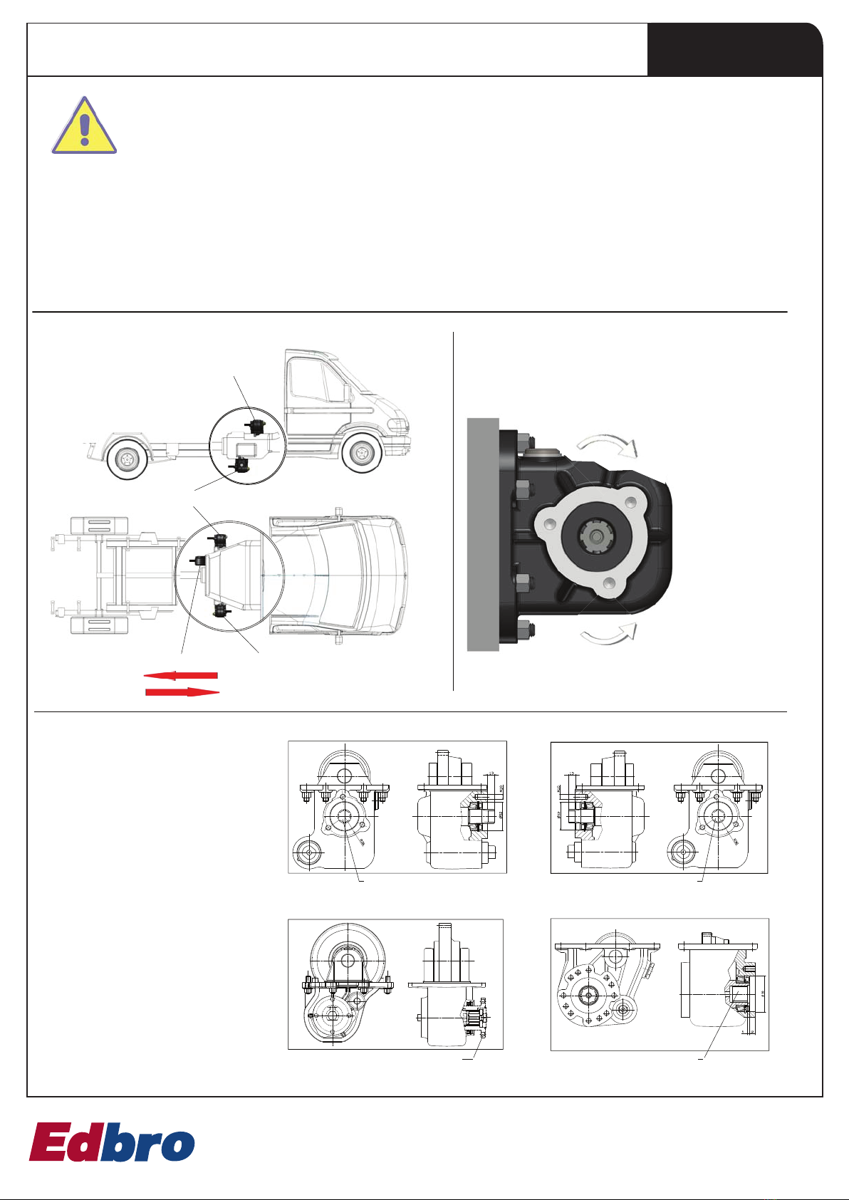
3 - GENERAL INFORMATION TO MOUNT POWER TAKE-OFFS
- Carefully follow these general assembly instructions, both as far as the safety precautions and the assembly stages of the PTOs are concerned.
- The general indications do not replace specic instructions contained in the PTOs, in the assembly kit or in the various assembly accessories
(adapters, auxiliary shafts, etc).
- It is necessary to also follow any instructions related to the vehicle gearbox.
- Install the PTO with the vehicle placed on a at surface, so that oil levels in the gearbox can be checked correctly.
- Only use the components contained in the PTO packaging and related accessories (assembly kit, auxiliary shafts, adapters).
- Only use gaskets supplied.
- Do not use sealing paste, unless explicitly indicated in the specic instructions.
- It is advisable to use a medium-strength threadlocker to tighten the studs and screws.
- Before assembling the PTO, check that the vehicles clutch and transmission work correctly and that the gearbox does no produce any
anomalous noises or issues in selecting gears.
TIGHTENING TORQUE (see note)
Thread diameter - Screw (mm) M8 M10 M12 UNC 3/8 UNC 7/16
Screws and nuts torque (Nm) 25 50 80 25 60
Studs torque (Nm) 6 10 18 10 20
For some aluminium gearboxes the tightening torque needs to be reduced
by 30%.
Note on the tightening torque: the tightening torques reported are only
means as a guide and do not replace the indications given by the vehicle’s
manufacturer of the gearbox manufacturer.
TABLE 3
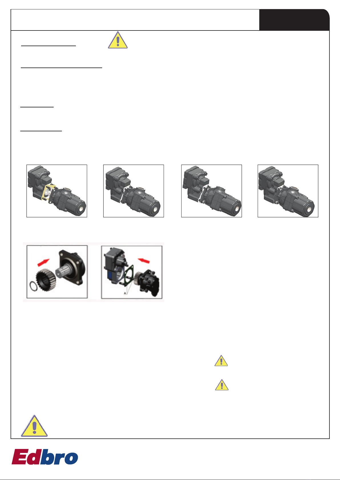
4.5 - If the PTO needs to be mounted
with studs, insert them (with the
short thread side) in the threaded
holes of the gearbox, using a
medium-strength threadlocker (LOC-
TITE 243, LOXEAL 55-03 or similar).
Tighten the studs using a torque like
the one indicated in TABLE 3 Chap.3 .
If the gearbox has feed-through
threaded holes, the threadlocker
should also have a sealing action
and it is necessary to check that the
studs do not interfere with the gea-
ring of with parts inside the gearbox.
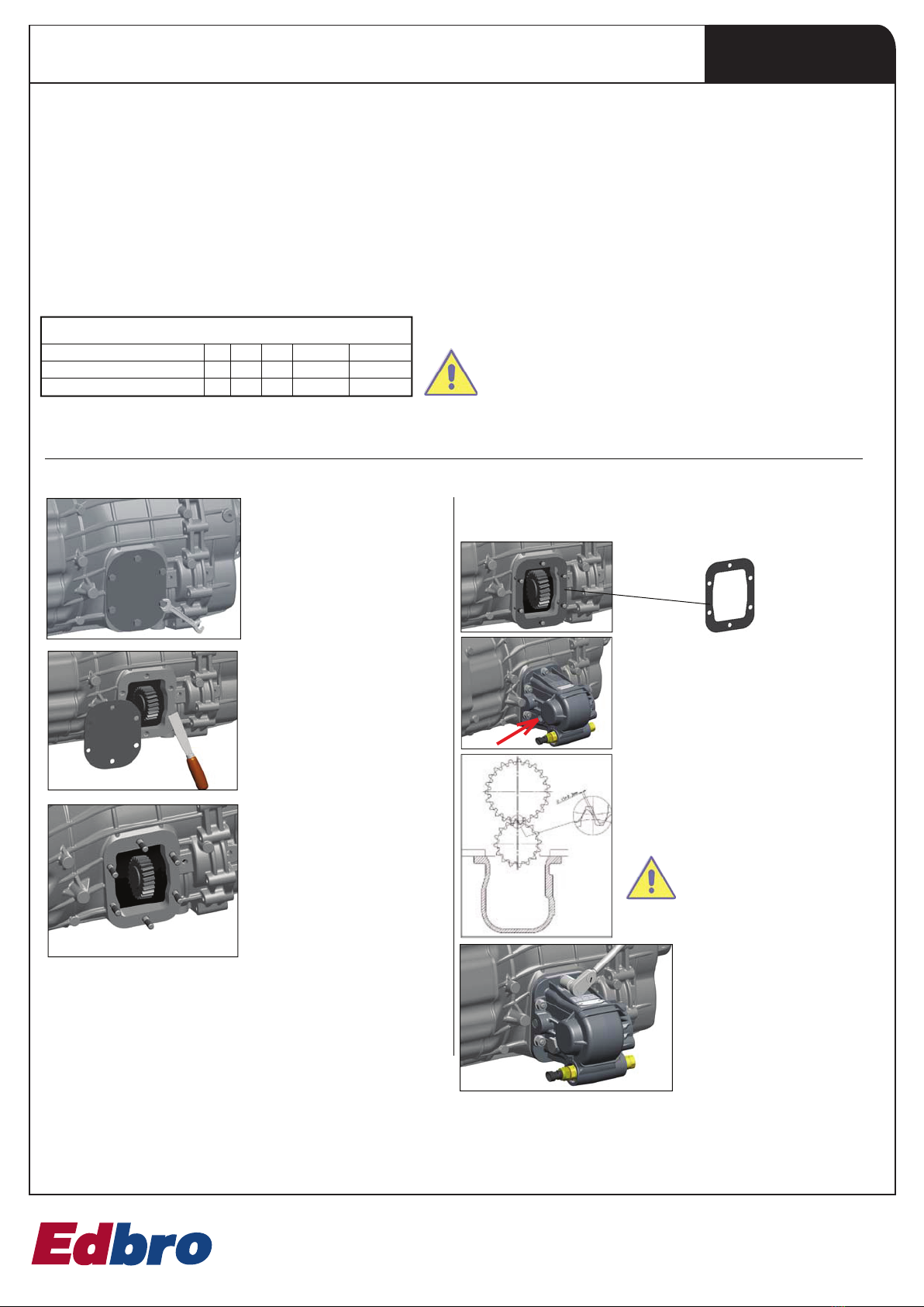
4.1 - Unscrew the drain plug
and remove the oil from the gear-
box. Screw the drain plug back
with the tightening torque indicated
in the gearbox’s operating manual.
4.2 - Identify the suitable gearbox
opening to mount the PTO and remo-
ve the cover with the related gasket.
4 - INSTALLATION OF SIDE MOUNT PTOS
4.3 - Check that the gearing is compa-
tible with the PTO’s gearing in terms of
position, inclination of the tooth and te-
ethsize.Thisneedstobecarriedoutasan
additional check that the right PTO has
been selected for the specied gearbox.
4.4 - Clean the surface of the ope-
ning, make sure no foreign mat-
ter is introduced in the gearbox.
4.6 - Position the sealing gasket.
4.7 - Install the PTO and tighten the nuts
with lower torque compared to the
nd xing torque.
4.9 - Once the optimal clearance
has been dened
tighten the nuts or the screws of the
PTO fully home with the tightening
torque shown in TABLE 3 Chap.3 .
4.10 - Top up the oil in the gearbox
bearing in mind that usually a side
mount PTO uses up approximately
0.5–0.8litresofoil. Installthecontrol
system. Start up the vehicle and en-
gage the PTO. Conduct the checks as
illustrated in the paragraphs below.
(A)
4.8 - Check, through the inspection hole
(indicated by the arrow) the clearan-
ce between the gearings. The clearan-
ce should be between 0.15 and 0.3 mm
(A) . The clearance is controlled manually
and therefore it cannot be precise. This is
why it is necessary to proceed by attem-
pts until the optimal clearance is achieved.