Ebyte E90-DTU Manual de usuario


Chengdu Ebyte Electronic Technology Co., Ltd. E90-DTU(400SL30P)User manual
Copyright ©2012–2019, Chengdu Ebyte Electronic Technology Co., Ltd
1
Contents
1. Introduction.................................................................................................................................................................3
1.1 Brief introduction..............................................................................................................................................3
1.1.1 Certificate...............................................................................................................................................3
1.1.2 Features.................................................................................................................................................. 3
2. Quick Start.................................................................................................................................................................. 5
3. Dimensions................................................................................................................................................................11
3.1 Parts description..............................................................................................................................................11
4. Interface definition....................................................................................................................................................13
4.1 Power interface............................................................................................................................................... 13
4.2 RS232..............................................................................................................................................................14
4.3 RS485..............................................................................................................................................................14
5. Technical specification..............................................................................................................................................15
5.1 Model specification.........................................................................................................................................15
5.2 General specification parameter..................................................................................................................... 15
5.3 Frequency and channel numbers.................................................................................................................... 15
5.4 Transmitting power......................................................................................................................................... 15
5.5 Air data rate.....................................................................................................................................................16
5.6 Current............................................................................................................................................................ 16
5.7 TX and RX FIFO and sub-packing method....................................................................................................16
6. Function Description.................................................................................................................................................16
6.1 Fixed Transmission(Hexadecimal)............................................................................................................16
6.2 Broadcast Transmission(Hexadecimal).....................................................................................................17
6.3 Broadcast Address........................................................................................................................................17
6.4 Monitor Address..............................................................................................................................................17
7.1 Normal mode(Mode 0)..............................................................................................................................18
7.2 Wor sending mode(Mode 1)......................................................................................................................18
7.3 WOR receiving mode(Mode 2).................................................................................................................18
8. Relay networking mode............................................................................................................................................ 19
9. Configuration instructions on computer................................................................................................................... 21
9.1 Configuration considerations..........................................................................................................................21
9.2 Factory default parameters............................................................................................................................. 21
9.3 Configuration software and parameter description........................................................................................ 21
Three main configuration function descriptions.......................................................................................... 22
Local configuration.......................................................................................................................................23
Remote configuration................................................................................................................................... 24
RSSI real-time monitoring............................................................................................................................25
9.4 Configuration parameter description of upper computer............................................................................... 25
10. Programming the modem........................................................................................................................................29
10.1 Connection diagram......................................................................................................................................29
11. Connection diagram in test and practical application.............................................................................................30
12.E90-DTU(SL Series)................................................................................................................................................31
13.Application field...................................................................................................................................................... 32
14.Operation notes........................................................................................................................................................ 33

Chengdu Ebyte Electronic Technology Co., Ltd. E90-DTU(400SL30P)User manual
Copyright ©2012–2019, Chengdu Ebyte Electronic Technology Co., Ltd
2
Important statement...................................................................................................................................................... 34
Revision history............................................................................................................................................................ 34
About us........................................................................................................................................................................ 34

Chengdu Ebyte Electronic Technology Co., Ltd. E90-DTU(400SL30P)User manual
Copyright ©2012–2019, Chengdu Ebyte Electronic Technology Co., Ltd
3
1. Introduction
1.1 Brief introduction
E90-DTU (400SL30P) is a true high-quality industrial-grade wireless digital radio. The power supply supports
electrostatic discharge anti-interference level 4 protection,fast transient anti-interference level 4 protection,surge impact
anti-interference Level 3 Protection. It can be used in industrial applications where the electromagnetic environment is
more complicated. The radio adopts LORA spread spectrum technology, and its powerful anti-interference ability makes
wireless communication more stable and reliable in the industrial field.
It has multiple transmission modes, working in the (410.125 ~ 493.125MHz) frequency band (default 433.125MHz),
the radio provides transparent RS232/RS485 interface, supports 8 ~ 28V voltage input. LoRa direct-sequence spread
spectrum technology will bring longer communication distances, and has the advantages of concentrated power density
and strong anti-interference ability. The module has a software FEC forward error correction algorithm, which has high
coding efficiency and strong error correction capability. In the case of sudden interference, it can actively correct the
interfered data packets, greatly improving reliability and transmission distance. In the absence of FEC, such packets can
only be discarded. The radio has data encryption function, and the data transmitted by the radio in the air has randomness.
The data interception is meaningless through strict encryption and decryption algorithms; the packet length setting is
supported, and different real-time and data packets are supported.
As a communication medium, wireless digital radio has the same scope as optical fiber, microwave and bright line:
it provides real-time and reliable data transmission of monitoring signals in private networks under certain special
conditions, with low cost and installation and maintenance. Convenient, strong diffraction ability, flexible network
structure and long coverage. It is suitable for multi-point and location dispersion, complex geographical environment, etc.
It can be connected with PLC, RTU, rain gauge, liquid level meter and other data terminals.
1.1.1 Certificate
E90-DTU is certified with “EMC high protection level certification”,ID: AGXA119W00150;
E90-DTU is certified with CMIIT ID:2017FP5780 by SRRC;
E90-DTU is certified with “Certificate of conformity on explosive application protection”,ID: 201711000975.;
E90-DTU is certified with “Electrostatic surge test report” by National Institute of Measurement and Testing
Technology,ID:CNEx18.1461;
E90-DTU is certified with “Certificate of Design Patent”,Patent Number:ZL 2016 3 0501980.3;
E90-DTUis certified with “Utility model patent certificate”,Patent Number:ZL 2016 2 1410691.3;
E90-DTU is certified with “CE” , ID:CCISE180514601V;
E90-DTU is certified with “FCC”, ID:2ALPH-E90-DTU;
E90-DTU is certified with “RoHS”,ID:DTI201807025245.
1.1.2 Features
supports electrostatic discharge anti-interference level 4 protection,fast transient anti-interference level 4
protection,surge impact anti-interference Level 3 Protection.
Environmental field strength dynamic indication, data packet RSSI dynamic indication;
Software and hardware dual watchdogs;

Chengdu Ebyte Electronic Technology Co., Ltd. E90-DTU(400SL30P)User manual
Copyright ©2012–2019, Chengdu Ebyte Electronic Technology Co., Ltd
4
Wireless air configuration;
Dust and moisture resistance;
The product is easy to use and configured by the host computer;
6-year warranty;
Using the latest LoRa technology, it has a longer distance and more powerful performance than traditional LoRa
digital radio stations;
Using military-grade LoRa modulation technology, with data encryption, the packet length is available for
configuration;
Large single package, single package is up to 240 bytes;
Simple and efficient power supply design, support power adapter or crimping mode, support 8~28V power supply.
Transmit power is up to 1W, multi-level adjustable, with all technical indicators meeting European industrial
standards.
Support LBT function, the transceiver automatically waits to send data according to the current ambient noise
intensity. The communication success rate of the module in harsh environments is greatly improved.
Remotely configure or read wireless module parameters by sending command packets wirelessly.
Support communication key function to effectively prevent data from being intercepted;
Multi-level relay networking can be realized ,which effectively extends communication distance for
ultra-long-distance communication.
With temperature compensation circuit, the frequency stability is better than ±1.5PPM.
Operating temperature range: -40 ° C ~ +85 ° C, to adapt to a variety of harsh working environment.
All-aluminum alloy casing, compact size, easy installation and good heat dissipation; perfect shielding design, with
good electromagnetic compatibility and strong anti-interference ability.
Multiple protection functions such as power reverse connection protection, over-current protection, and antenna
surge protection greatly increase the reliability of the device.
Powerful software functions, all parameters can be programmed: such as power, frequency, air data rate, address ID,
etc.
Ultra-low power consumption, standby current is only 12V / 42mA (lower power consumption in power saving
mode and sleep mode);
with built-in watchdog and precise time layout, once an exception occurs, the transceiver will automatically restart,
and continue to work according to the previous parameters.

Chengdu Ebyte Electronic Technology Co., Ltd. E90-DTU(400SL30P)User manual
Copyright ©2012–2019, Chengdu Ebyte Electronic Technology Co., Ltd
5
2. Quick Start
You need to prepare items below,
Note: The distance between two high-power DTUs should be more than 1 meter, otherwise it may cause damage!
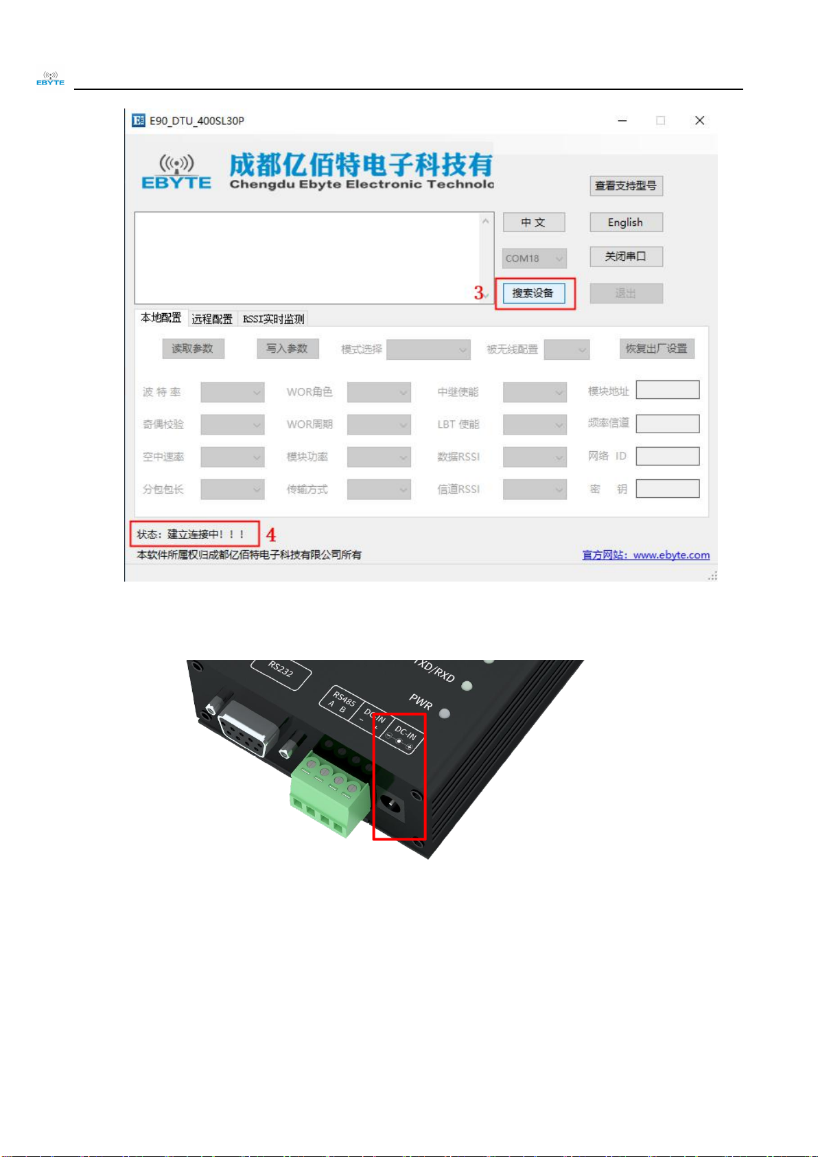
1. First install the antenna for the digital radio station, and then use USB to RS-232 or USB to RS-485 to connect
the computer to the digital radio station. The computer opens the host computer software, selects and opens the serial port,
and clicks to search for the device (at this time the host computer The status bar shows: Establishing connection !!!).
Chengdu Ebyte Electronic Technology Co., Ltd. E90-DTU(400SL30P)User manual
Copyright ©2012–2019, Chengdu Ebyte Electronic Technology Co., Ltd
6
2. Then plug in the radio power, and the device will automatically connect with the host computer (the status bar of
the host computer will display: The configuration connection is successful !!!)

Chengdu Ebyte Electronic Technology Co., Ltd. E90-DTU(400SL30P)User manual
Copyright ©2012–2019, Chengdu Ebyte Electronic Technology Co., Ltd
7
3. After the connection is established, you can use the host computer to configure the parameters of the radio, or
remotely configure other module radios.
Please read the parameters before configuration. After selecting the parameters that need to be set and clicking the
write parameter button, the parameters can be written into the radio, and it will take effect after exiting the
configuration mode.


Chengdu Ebyte Electronic Technology Co., Ltd. E90-DTU(400SL30P)User manual
Copyright ©2012–2019, Chengdu Ebyte Electronic Technology Co., Ltd
9
set working mode and parameters (no need to restart the radio);
4. Communication test, start two serial port debugging assistants, select the serial port baud rate and verification method
that are consistent with the radio parameters, and then realize the serial port transparent transmission (note: the
parameters of the two radios need to be set the same);
Otros manuales para E90-DTU
25
Este manual sirve para los siguientes modelos
1
Tabla de contenidos
Otros manuales de Transceptor de Ebyte

Ebyte
Ebyte E810 Series Manual de usuario

Ebyte
Ebyte E70-915T14S Guía de configuración

Ebyte
Ebyte E62-433T20D Manual de usuario

Ebyte
Ebyte E90-DTU Manual de usuario

Ebyte
Ebyte E840-DTU Manual de usuario
 Manual de usuario")
Ebyte
Ebyte E90-DTU(433L30E) Manual de usuario

Ebyte
Ebyte E90-DTU Manual del operador

Ebyte
Ebyte E831-RTU Series Manual de usuario

Ebyte
Ebyte E78-400M22S1C Manual de usuario

Ebyte
Ebyte E34-2G4H20D Manual de usuario


