
DuroStar DS4000WGE Manual de usuario

1
DS4000WGE
Gasoline Generator/Welder
Owner’s Manual
Max Tool Customer Service
customer_service@maxtool.com
or call 1-800-629-3325 (option 3) Monday -Thursday 6am to 7pm, Friday - Saturday 6am to 3pm. PST
Product Support (Product: information, application, service info & warranty questions)
or call 1-800-629-3325 (option 3) Monday -Thursday 6am to 7pm, Friday - Saturday 6am to 3pm. PST
This manual provides information regarding the operation and maintenance of these products. We
have made every effort to ensure the accuracy of the information in this manual. We reserve the right
to change this product at any time without prior notice.
Please keep this manual available to all users during the entire life of the generator/welder.

2
WARNING:
The engine exhaust from this product contains chemicals known to the State of California to cause
cancer, birth defects or other reproductive harm.
WARNING:
The generator is a potential source of electrical shock if misused. Do not expose the generator
to moisture, rain or snow. Do not let the generator get wet, and do not operate it with wet hands.
Keep this owner's manual handy, so you can refer to it at any time. This owner’s manual is
considered a permanent part of the generator and should remain with the generator if resold.
The information and specifications included in this publication were in effect at the time of approval
for printing. Our company reserves the right, however, to discontinue or change specifications or
design at any time without notice and without incurring any obligation whatever. No part of this
publication may be reproduced without written permission.
Congratulations on your selection of our generator/Welder. We are certain you will be pleased with
your purchase of one of the finest generators/Welders on the market.
We want to help you get the best results from your new generator/welder and to operate it safely.
This manual contains the information on how to do that, please read it carefully.
As you read this manual, you will find information preceded by a symbol. That information is
intended to help you avoid damage to your generator/welder, other property, or the environment.
We suggest you read the warranty policy to fully understand its coverage and your responsibilities
of ownership. The warranty policy is a separate document that should have been given to you by your
dealer.
When your generator/Welder needs scheduled maintenance, keep in mind that our servicing dealer
is specially trained in servicing our generators/welders. Your authorized our servicing dealer is
dedicated to your satisfaction and will be pleased to answer your questions and concerns.

3
A FEW WORDS ABOUT SAFETY
Your safety and the safety of others is very important. And using this generator/Welder safely is an
important responsibility.
To help you make informed decisions about safety, we have provided operating procedures and
other information on labels and in this manual. This information alerts you to potential hazards that
could hurt you or others.
Of course, it is not practical or possible to warn you about all the hazards associated with operating
or maintaining a generator/Welder. You must use your own good judgment.
You will find important safety information in a variety of forms, including;
·Safety Labels — on the generator/Welder.
·Safety Messages — Preceded by a safety alert symbol and one of three signal words, DANGER,
WARNING, or CAUTION.
These signal words mean:
DANGER: You WILL be KILLED or SERIOUSLY HURT if you don't follow instructions.
WARNING: You WILL be KILLED or SERIOUSLY HURT if you don't follow instructions.
CAUTION: You CAN be HURT if you don't follow instructions.
·Safety Headings — such as IMPORTANT SAFETY INFORMATION.
·Safety Section — such as GENERTOR/WELDER SAPETY.
·Instructions — how to use this generator/Welder correctly and safely.
This entire book is filled with important safety information — please read it carefully.

4
CONTENTS
SAFETY.......................................................................................................................................................... 1
Safety Label Locations................................................................................................................................ 1
Safety Information.......................................................................................................................................1
COMPONENT INDENTIFICATION............................................................................................................ 3
CONTROLS.................................................................................................................................................... 4
Engine Switch..............................................................................................................................................4
Recoil Starter...............................................................................................................................................4
Fuel Valve Lever.........................................................................................................................................5
Choke Rod...................................................................................................................................................5
Circuit Breaker............................................................................................................................................5
Oil Alert System.......................................................................................................................................... 6
DC Receptacle.............................................................................................................................................6
A/C (Weld) Selector Switch........................................................................................................................6
Welding Cable Terminal............................................................................................................................. 7
Welding Current Adjust System.................................................................................................................. 7
GENERATOR/WELDER USE......................................................................................................................8
Connections to Building Electrical System.................................................................................................8
AC Operation .............................................................................................................................................. 8
Welding....................................................................................................................................................... 9
Selecting the Correct Welding Current..................................................................................................... 10
Welding Cable Selection...........................................................................................................................10
Welding Duty Cycle..................................................................................................................................10
Polarity Selection ...................................................................................................................................... 10
High Altitude Operation............................................................................................................................11
PRE-OPERATION CHECK.........................................................................................................................12
Engine Oil .................................................................................................................................................12
Fuel Recommendation...............................................................................................................................12
STARTING THE ENGINE/STOPPING THE ENGINE ............................................................................. 15
MAINTENANCE ......................................................................................................................................... 16
The Importance of Maintenance................................................................................................................16
Maintenance Safety................................................................................................................................... 16
Emission Control System Information......................................................................................................17
Air Index ...................................................................................................................................................18
Maintenance Schedule...............................................................................................................................19
Engine Oil Change ....................................................................................................................................19
Air Cleaner Service................................................................................................................................... 20
Fuel Sediment Cup Cleaning.....................................................................................................................21
Spark Plug Service ....................................................................................................................................21
TRANSPORTING/STORAGE.....................................................................................................................23
WIRING DIAGRAM.................................................................................................................................... 25
SPECIFICATIONS....................................................................................................................................... 26
WHEEL LIT .......................................................................................................................................... 27

5
SAFETY
SAFETY LABEL LOCATIONS
These labels warn you of potential hazards that can cause serious injury. Read them carefully.
If a label comes off or becomes hard to read, contact your Generator dealer for a replacement.
SAFETY INFORMATION
Our generator/welders are designed to give safe and dependable service if operated according to
instructions. Read and understand this owner's manual before operating your generator/welder. You
can prevent accidents by being familiar with your generator/welder's controls, and by observing safe
operating procedures.
Operator Responsibility
•Know how to stop the generator/welder quickly in case of emergency.
•Understand the use of all generator/welder controls, output receptacles, and connections.
•Be sure that anyone who operates the generator/welder receives proper instruction. Do not let
children operate the generator/welder without parental supervision.
Carbon Monoxide Hazards
•Exhaust contains poisonous carbon monoxide, a colorless and odorless gas. Breathing exhaust can
cause loss of consciousness and may lead to death.
•If you run the generator/welder in an area that is confined, or even partially enclosed, the air you
breathe could contain a dangerous amount of exhaust gas. To keep exhaust gas from building up,
provide adequate ventilation.
Electric Shock Hazards
•The generator/welder produces enough electric power to cause a serious shock or electrocution if
misused.
•Using a generator/welder or electrical appliance in wet conditions, such as rain or snow, or near a
pool or sprinkler system, or when your hands are wet, could result in electrocution. Keep the
generator/welder dry.
•If the generator/welder is stored outdoors, unprotected from the weather, check all electrical
components on the control panel, before each use. Moisture or ice can cause a malfunction or short
circuit in electrical components which could result in electrocution.
•Do not connect to a building's electrical system unless an isolation switch has been installed by a
qualified electrician.
Fire and Burn Hazards
•The exhaust system gets hot enough to ignite some materials.
—Keep the generator/welder at least 1 meter (3 feet) away from buildings and other equipment
during operation.
—Do not enclose the generator/welder in any structure.

6
—Keep flammable materials away from the generator/welder.
•The muffler becomes very hot during operation and remains hot for a while after stopping the engine.
Be careful not to touch the muffler while it is hot. Let the engine cool before storing the
generator/welder indoors.
•Gasoline is extremely flammable and is explosive under certain conditions. Do not smoke or allow
flames or sparks where the generator/welder is refueled or where gasoline is stored. Refuel in a
well-ventilated area with the engine stopped.
•Fuel vapors are extremely flammable and may ignite after the engine has started. Make sure that any
spilled fuel has been wiped up before starting the generator/welder.
•Use adequate eye protection. Eye protection is of the utmost importance, not only for the operator,
but also for any other personnel in the vicinity while welding is being done. Eye hazards include arc
glare, reflected glare, stray flashes, sparks, and flying bits of molten metal.
• NEVER LOOK AT WELDINGARC WITH UNPROTECTED EYES. Looking at a welding arc
with unprotected eyes can cause severe pain, temporary or even permanent blindness.
•Use a helmet or hand-held shield with a #10 or darker filter lens. Filter lenses eliminate the harmful
effects of infrared and ultraviolet radiation from the arc and reduce the glare from the arc light as
well.
•Wear protective clothing such as leather gloves, cap, sleeves, jacket, apron, and high-top safety shoes.
All outer clothing must be free of oil and grease.

7
COMPONENT IDENTIFICATION
•Record the engine and frame serial numbers for your future reference. Refer to these serial numbers
when ordering parts, and when making technical or warranty inquiries.

8
CONTROLS
Engine Switch
To start and stop the engine.
Switch position:
OFF: To stop the engine.
ON: To run the engine.
Recoil Starter
To start the engine, pull the starter grip lightly until resistance is felt, then pull briskly.
NOTICE:
Do not allow the starter grip to snap back against the engine. Return it gently to prevent damage
to the starter.

9
Fuel Valve Lever
The fuel valve is located between the fuel tank and carburetor. When the fuel valve lever is in the
ON position, fuel is allowed to flow from the fuel tank to the carburetor. Be sure to return the fuel
lever to the OFF position after stopping the engine.
Choke Rod
The choke is used to provide an enriched fuel mixture when starting a cold engine. It can be opened
and closed by operating the choke rod manually. Pull the rod out toward CLOSED to enrich the
mixture for cold starting.
Circuit Breaker
The circuit breaker will automatically switch OFF if there is a short circuit or a significant overload
of the generator at the receptacle. If the circuit breaker is switched OFF automatically, check that the
appliance is working properly and does not exceed the rated load capacity of the circuit before
switching the circuit breaker ON again.
The circuit breaker may be used to switch the generator power ON or OFF.
10
Oil Alert System
The Oil Alert System is designed to prevent engine damage caused by an insufficient amount of oil
in the crankcase. Before the oil level in the crankcase can fall below a safe limit, the oil alert system
will automatically stop the engine (the engine switch will remain in the ON position). If the engine
stops and will not restart, check the engine oil level before troubleshooting in other areas.
DC Receptacle
The DC receptacle may ONLY be used for charging 12 volt automotive type batteries.
The battery must be connected to the generator DC receptacle with the proper polarity (battery
positive to generator positive (+) and battery negative to the generator negative (-)).
WARNING:
Do not start the vehicle while the battery charging cable is connected and the generator is running.
The vehicle or the generator may be damaged.
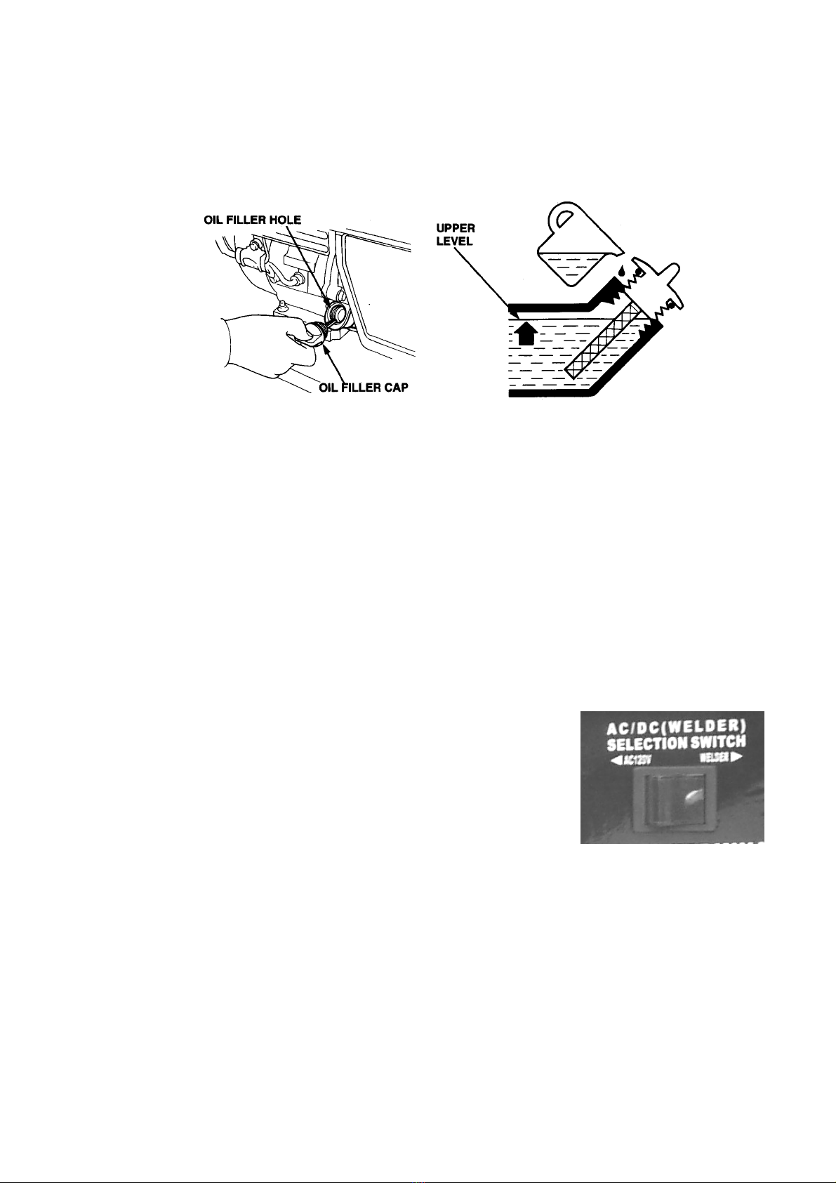
AC/DC (Weld) Selector Switch
The AC/DC (Weld) selector switch is located on the control panel.
•To avoid accidental arcing, one cable end should be firmly attached
to the object to be welded, and the electrode holder at the end of the
other cable should be held in the operator's hand. DC voltage is
present at the welding terminals at all times, regardless of the
position of the AC/DC (WELD) selector.
•Under no circumstances should any type of electrical appliance be
plugged into any of the AC receptacles when the selector is in the DC (WELD) position. AC voltage
is present at the AC receptacle at all times, regardless of the position of the AC/DC (WELD) selector.
However, when this selector is in the DC (WELD) position, the AC voltage is unregulated and
fluctuates considerably.
Otros manuales para DS4000WGE
1
Tabla de contenidos
Manuales populares de Sistema de soldadura de otras marcas


TAFA
TAFA 30*8B35 Manual de usuario

Lincoln Electric
Lincoln Electric INVERTEC V350-PRO CE Manual de usuario

ESAB
ESAB Buddy Arc 145 Manual de usuario

CIGWELD
CIGWELD 636804 Guía rápida

Red-D-Arc
Red-D-Arc DC-400 Manual de usuario

Hobart Welding Products
Hobart Welding Products Spool Gun DP 3035-10 Manual de usuario


