
Dong Jin DCS - Series Guía de inicio rápido

HIGH SPEED CIRCULAR SAWING MACHINE
ISO9001/CE
SINCE1980
OPERATIONAL
M A N U A L
DCS-100H
DCS-125H
Thank you for purchasing
Dong Jin’s High Speed Circular
Sawing Machine DCS- series.
In order to use DCS- series
more efficiently, please read
this manual before operation.
ADDRESS
:
115BL 4LT NAMDONG Industrial complex, 685-3
Gojan-dong, Namdong-gu, Incheon, Korea
T E L
:
82-32-813-3041~4
F A X
:
82-32-672-0111
W E B
:
www.djmc.co.kr
E - m a i l
:

2
Please read the safety instruction carefully!
Before installation, operation and maintenance of the
machine, please read the next page Description of
Safety Precautions and Warning Signs carefully.
You should not try to install or operate this machine
until you have read this manual carefully and
understood its whole content. Otherwise, injuries and
damages might be caused by so doing.
Operators have to endure trainings of safety and
machine operations. After certified and authorized by
the employer, they can thus be allowed to operate the
machine.
If machine is treated improperly or safety regulations
are ignored, injuries and damages will be caused by so
doing.
Please contact us, once questions regarding this
manual or safety regulations arise.
This manual is deemed as an important document
attached to this machine. Please hand it over to the next
owner when the machine’s ownership is changed or
transferred.

3
This warning symbolized figure means Warning, no matter
when it appears in this manual or machine’s labels you must
take all the necessary of safety precautions.
They indicate danger of injury or death!!
This warning symbolizes figure means High Voltage Electrical
Facilities, no matter when they appear in this manual or
machine’s labels. You must take all the necessary of safety
precautions.
They indicate electrical shock of injuries or death!!!
Definition of Warning Signs
DANGER
The sign of “DANGER” in this manual or on the machine’s labels means loss of
life, severe personal injury or substantial property damage WILL entail if proper
safety precautions are not taken.
WARNING
The sign of “WARNING” in this manual or on the machine’s labels means loss
of life, severe personal injury or substantial property damage CAN entail if
proper safety precautions are not taken.
CAUTION
The sign of “CAUTION” in this manual or on the machine’s labels means minor
injury or property damage CAN entail proper precautions are not taken.
DANGER
Children and irrelevant operators must be prevented from accessing or
approaching the machine and strictly prohibited to touch any switch and knob.
DANGER AND WARNING
This manual should be placed in an obvious and accessible location where
people everyone is informed. The correct location and usage of “EMERGENCY”
button should be informed to everyone. Once hazardous condition happens,
operators on the site have to press “EMERGENCY” button to shut off the
machine.

4
CONTENTS
1. Introduction
(1) Introduction ················································································· 6
(2) Specification ················································································ 7
(3) Part Name ···················································································· 8
2. Layout Drawing ·············································································· 9
3. Installation and Moving
(1) Installation of the machine ·························································· 10
(2) Transportation ············································································ 11
(3) Cleaning before operation ···························································· 12
(4) Coolant ······················································································ 12
(5) Power Source Facility ·································································· 13
4. The description of Control box ······················································ 14
5. Operation
(1) The adjustment of cutting stroke ·················································· 17
(2) The adjustment of vise stroke ······················································ 18
(3) Angular Cut ················································································ 19
(4) Fixed Vise Jaw ············································································ 20
(5) Stopper block ············································································· 20
(6) Saw Blade ··················································································· 21
(7) Vise Pressure Adjustment ···························································· 22
(8) Timer Adjustment ······································································· 23
(9) Saw Head Speed Control ······························································ 24

5
6. Cutting Procedure ········································································ 25
7. Hydraulic System
(1) Hydraulic Circuit ········································································· 26
(2) Parts List ···················································································· 27
8. Electric System
(1) Electric Circuit ············································································ 28
(2) Part List ····················································································· 30
9. Maintenance
(1) Chip Scrapper ············································································· 32
(2) Chip Box ···················································································· 32
(3) Coolant Tank ·············································································· 32
(4) Assembly DWG. ·········································································· 33
①Stand Assembly ············································································ 33
②Table Assembly ············································································· 35
③Column Assembly ·········································································· 37
④Coolant & Blade Cover Assembly ······················································· 39
⑤Moving Vise Assembly ···································································· 41
⑥Gear Box Assembly ········································································ 43

6
1. Introduction
(1) Introduction
WARNING
Any modification and change in usage of the machine is highly
prohibited for unexpected damage or hazard may occur.
Since the Saw Head of the machine cuts down smoothly the material
through the guide on the vertical column, the surface of material is very
clean and has almost no burr. This machine is very efficient for the precise
cutting.
The gear box consists of several “Carburizing Heat-Treatment”Helical
Gears, which are very durable. There is almost no noise and no vibration.
High drive-efficiency makes it possible to perform a powerful and fast
cutting.
Specially designed vise structure brings it to perform a powerful clamp
capacity. Knurling process and a high frequency heat treatment of vise
surface help the material to stick to the vise well. The support vises can be
adjustable depending on the length of material and they can move freely
according to operator’s preference.
The Sawing Head can be adjusted from left 45° to right 40° in order to
work the angular cutting.
The chip of cut-material on the saw blade can be rejected by chip ejector.
The cleaning of coolant tank is very easy.
You can keep the tools and blade in the front drawer inside of stand.

7
(2) Specification
M O D E L
DCS-100H
DCS-125H
C U T T I N G
C A P A C I T Y
R O U N D
9080mm
4590mm
90125mm
45110mm
S Q U R E
9090x90mm
4580x80mm
90116x116mm
45108x108mm
RECTANGULAR
90140x75mm
4590x75mm
90170x100mm
45130x90mm
S A W H E A D
S P I N D L E
H S S S A W
B L A D E
300mmx40mmx2.5t
360mmx40mmx3t
M O T O R
1.5kW•2/4P•220V/380V•3
R P M
50Hz22/44
60Hz27/52
50Hz19/38
60Hz23/46
C H I P S C R A P P E R
URETHAN ROLLER
S A W H E A D M O V E M E N T
HYDRAULIC AUTOMATIC
M A I N V I S E
HORIZONTAL TYPE(HYDRAULIC)
C U T F E E D I N G S P E E D
3~300mm/min
H Y D R A UL I C
D E V I C E
PUMP MOTOR
0.75kW
W O R K I N G
P R E S S U R E
30kgf/㎠
O I L T A N K
V O L U M E
45ℓ
C O O L A N T
C O O L A N T
P U M P
60Wx4Px220Vx3
C O O L A N T
V O L U M E
14ℓ
APPEARANCE
S I Z E
(LxWxH)
1045x1135x1610mm
1045x1150x1700mm
W E I G H T
550kg
607kg
A C C E S S O R I E S
SPANNER: 24mm, 22mm, 19mm, 17mm
WRENCH: 1set
CONSENT: 1EA

8
(3) Part Name
Fig.1
1
C Y L I N D E R
10
B L A D E C O V E R
2
M O T O R
11
S U P P O R T V I S E
3
C O N T R O L B O X
12
MAIN VISE CYLINDER
4
C U T T I N G S T R O K E
A D J U S T D E V I C E
13
H A N D L E
5
G E A R B O X
14
M A I N V I S E
6
R O U N D T A B L E
L O C K S C R E W
15
R O U N D T A B L E
7
SPEED CONTROL VALVE
16
C O L U M N
8
S T A N D
17
T A B L E
9
B E L T C O V E R
18
F I X E D V I S E
9
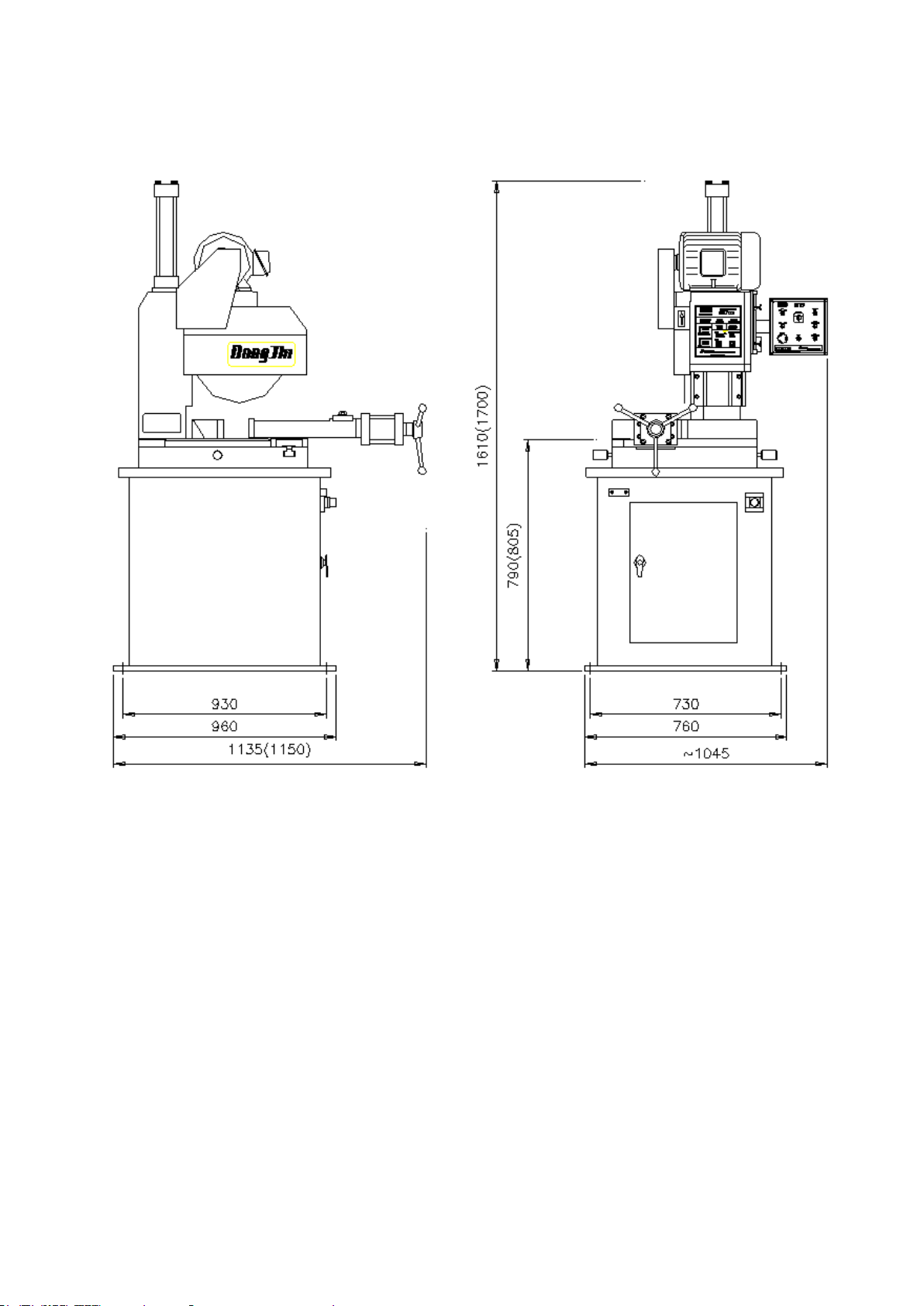
2. Layout Drawing
Fig.2

10
3. Installation and Moving
(1) Installation of the Machine
CAUTION
When you install the machine, please don’t give a severe hit or
impact to its main body. Please be careful not to break the gauges,
sensors and other fragile important parts on the machine.
The location of installation should be safe from vibration and other
influence of machines. Also its floor should be flat and strong enough to
endure the weight of machine.
Este manual sirve para los siguientes modelos
2
Tabla de contenidos


