DKS HSG-G122 Manual de usuario

NOTES
1. MODEL : HSG-G1222 외/ NOBRAND
2. MATERIAL : 모조지, 100g/㎡, WHITE
3. COLOR : TEXT- BLACK
4. SIZE : 105(+/-5)mm x 148(+/-5)mm
5. LABEL : --------------------------------------
6. ANY CHANGE OR ALTERNATION MUST BE
APPROVED BY HITRON DESIGN TEAM.
UNLESS OTHERWISE SPECIFIED
ALL DIMENSIONS ARE IN MM.
- TOLERANCE
DESCRIPTION/MATERIAL
Quick Guide
PARTS LIST
DO NOT SCALE
TITLE
MATERIAL CHKED
APPROVALS DATE
COLOR DRAWN
H.I.AHN
D.G.KIM A6 B
10-18-12
10-18-12 SIZE
SCALE
REV
ITEM QTY
LABEL
MANUAL
GUIDE
+/-3
+/-5
+/-5
50302977
2
3
협
의
개발
민철기
PRODUCTION RELEASE & REVISION
REV
A
DESCRIPT’N/BUYER
INITIAL ----------------- 50302977 H.I.AHN D.G.KIM 09-19-12
B INITIAL ----------------- 50302977 H.I.AHN D.G.KIM 10-18-12
DWG No PATRS No. BY CHK DATE
10-18-12
105(+/-5)mm
148(+/-5)mm
REV B : 앞뒤표지수정재고없음즉시적용

INSTALLATION / OPERATION
USER
’
S MANUAL
Full HD-SDI CAMERA
Please read this manual thoroughly before use, and keep it handy for future reference.

WARNING
TO REDUCE THE RISK OF FIRE OR ELECTRIC SHOCK, DO NOT EXPOSE THIS PRODUCT TO RAIN OR MOISTURE. DO
NOT INSERT ANY METALLIC OBJECTS THROUGH THE VENTILATION GRILLS OR OTHER OPENINGS ON THE EQUIPMENT.
CAUTION
CAUTION
RISK OF ELEC
T
RNIC SHOCK
DO NOT OPEN
CAUTION: TO REDUCE THE RISK OF ELECTRIC SHOCK,
DO NOT REMOVE COVER (OR BACK).
NO USER-SERVICEABLE PARTS INSIDE.
REFER SERVICING TO QUALIFIED SERVICE PERSONNEL.
EXPLANATION OF GRAPHICAL SYMBOLS
The lightning flash with arrowhead symbol, within an equilateral triangle, is intended to alert the user to
the presence of uninsulated "dangerous voltage" within the product's enclosure that may be of sufficient
magnitude to constitute a risk of electric shock to persons.
The exclamation point within an equilateral triangle is intended to alert the user to the presence of
important operating and maintenance (servicing) instructions in the literature accompanying the product.
PRECAUTIONS
Safety ------------------------ Installation -------------------------
Cleaning ------------------------
Should any liquid or solid ob
j
ect fall into the cabinet,
unplug the unit and have it checked by the qualified
personnel before operating it any further.
Unplug the unit from the wall outlet if it is not going to
be used for several days or more. To disconnect the
cord, pull it out by the plug. Never pull the cord itself.
Allow adequate air circulation to prevent internal heat
build-up. Do not place the unit on surfaces (rugs,
blankets, etc.) or near materials(curtains, draperies)
that may block the ventilation holes.
Height and vertical linearity controls located at the rear
panel are for special adjustments by qualified
personnel only.
Do not install the unit in an extremely hot or humid
place or in a place subject to excessive dust, mechanical
vibration.
The unit is not designed to be waterproof.
Exposure to rain or water may damage the unit.
Clean the unit with a sli
g
htly damp soft cloth.
Use a mild household detergent. Never use strong
solvents such as thinner or benzene as they might
damage the finish of the unit.
Retain the original carton and packing materials for safe
transport of this unit in the future.

FCC COMPLIANCE STATEMENT
FCC INFORMATION: THIS EQUIPMENT HAS BEEN TESTED AND FOUND TO COMPLY
WITH THE LIMITS FOR A CLASS A DIGITAL DEVICE, PURSUANT TO PART 15 OF THE FCC RULES. THESE
LIMITS ARE DESIGNED TO PROVIDE REASONABLE PROTECTION AGAINST HARMFUL INTERFERENCE
WHEN THE EQUIPMENT IS OPERATED IN A COMMERCIAL ENVIRONMENT. THIS EQUIPMENT
GENERATES, USES, AND CAN RADIATE RADIO FREQUENCY ENERGY AND IF NOT INSTALLED AND USED
IN ACCORDANCE WITH THE INSTRUCTION MANUAL, MAY CAUSE HARMFUL INTERFERENCE TO RADIO
COMMUNICATIONS. OPERATION OF THIS EQUIPMENT IN A RESIDENTIAL AREA IS LIKELY TO CAUSE
HARMFUL INTERFERENCE IN WHICH CASE THE USER WILL BE REQUIRED TO CORRECT THE
INTERFERENCE AT HIS OWN EXPENSE.
CAUTION:CHANGES OR MODIFICATIONS NOT EXPRESSLY APPROVED BY THE PARTY
RESPONSIBLE FOR COMPLIANCE COULD VOID THE USER'S AUTHORITY TO OPERATE THE EQUIPMENT.
CE COMPLIANCE STATEMENT
THIS CLASS A DIGITAL APPARATUS COMPLIES WITH CANADIAN ICES-003.
CET APPAREIL NUMÉRIQUE DE LA CLASSE A EST CONFORME À LA NORME NMB-003 DU CANADA.
WARNING
This is a Class A product. In a domestic environment this product may cause radio interference in which case the user
may be required to take adequate measures.
3

IMPORTANT SAFETY INSTRUCTIONS
1. Read these instructions.
2. Keep these instructions.
3. Heed all warnings.
4. Follow all instructions.
5. Do not use this apparatus near water.
6. Clean only with dry cloth.
7. Do not block any ventilation openings. Install in accordance with the
manufacturer’s instructions.
8. Do not install near any heat sources such as radiators, heat registers, stoves,
c or other apparatus (including amplifiers) that produce heat.
9. Do not defeat the safety purpose of the polarized or grounding-type plug.
A polarized plug has two blades with one wider than the other. A grounding
type plug has two blades and a third grounding prong. The wide blade or the
third prong are provided for your safety. If the provided plug does not fit into
your outlet, consult an electrician for replacement of the obsolete outlet.
10. Protect the power cord from being walked on or pinched particularly at plugs
convenience receptacles, and the point where they exit from the apparatus.
11. Only use attachments/accessories specified by the manufacturer.
12. Use only with the cart, stand, tripod, bracket, or table
specified by the manufacturer, or sold with the apparatus.
When a cart is used, use caution when moving the
cart/apparatus combination to avoid injury from tip-over.
13. Unplug this apparatus during lightning storms or when
unused for long periods of time.
14. Refer all servicing to qualified service personnel. Servicing is
required when the apparatus has been damaged in any way, such as power-
supply cord or plug is damaged, liquid has been moisture, does not operate
normally, or has been dropped.
15. CAUTION – THESE SERVICING INSTRUCTIONS ARE FOR USE BY
QUALIFIED SERVICE PERSONNEL ONLY. TO REDUCE THE RISK
OF ELECTRIC SHOCK DO NOT PERFORM ANY SERVICING OTHER
THAN THAT CONTAINED IN THE OPERATING INSTRUCTIONS
UNLESS YOU QRE QUALIFIED TO DO SO.
16. Use satisfy clause 2.5 of IEC60950-1/UL60950-1 or Certified/Listed Class
2 power source only.
4

TABLE OF CONTENTS
CONTENTS OF PACKAGE -------------------------------------------------------------3
INTRODUCTION----------------------------------------------------------------------------6
CAMERA OVERVIEW ---------------------------------------------------------------------7
CAMERA INSTALLATION----------------------------------------------------------------8
OSD Menu Setup ------------------------------------------------------------------10
CAMERA OPERATION --------------------------------------------------------------11
CONNECTIONS / DAY&NIGHT IN & ALARM OUT TERMINALS -------------14
SPECIFICATIONS ---------------------------------------------------------------------------------- 16
CONTENTS OF PACKAGE
Installation of the camera must be performed by qualified service personnel in accordance with all local and national
electrical and mechanical codes.
Carefully remove the color camera and its accessories from the carton and verify that they were not damaged in
shipment.
The content of the package includes:
1. HD-SDI DOME Camera
2. Manual
3. Accessory kit for installing Dome Camera
4. Template sheet
5. Extension connector kit
5

INTRODUCTION
Full HD 2Mega pixel Camera HD-SDI
1080@30fps HD-SDI & Composite Video OUT.
Features:
Full HD (1920x1080p) Real Time
High definition, 1080p video over 100m of RG59 or equivalent cable
Advanced Technology for Surveillance
-WDR( Wide Dynamic Range ) / BLC
- 3D-Digital Noise Reduction
- Digital Image Stabilization
- Digital Slow Shutter
- Digital Zoom x10 Max
- Removable IR Cut Filter for Day & Night
- Privacy Zone Masking
- Video Motion Detection
-Day & Night function
Single 75Ωcoaxial bi-directional RS 485 interface
RS 485 interface
HD-SDI Out/ Alarm OUT / D&N IN
User Certified / Listed Class 2 power source only
Operates in 12VDC or 24VAC
6

CAMERA OVERVIEW
TOP VIEW
Lens: Allows wide area to be monitored
BNC Cable: HD-SDI OUT & Extension cable
Connection Cable
①BNC Connector : HD-SDI Output
②Main POWER connection
- RED : DC12V or AC24V
- Black : GND or AC24V
③Heater POWER connection
- Gray : DC12V or AC24V
- White : GND or AC24V
④Connection
- BLUE : Alarm Input
- BROWN : GND
- ORANGE : GND
- PURPLE : D/N Input
- GREEN : 485-
- YELLOW: RS 485+
7
INSTALLATION
-------------------------------------------------------------------------------------------------------------------------
Before Installation
Before installing the camera, thoroughly familiarize yourself with the information in this section of the manual.
- Recommends connecting the camera to a network that use a DHCP (Dynamic Host Configuration Protocol)
server to address devices.
- To ensure secure access to the IP camera, place the camera behind a firewall when it is connected to a
network.
Starting Installation
Base Installation
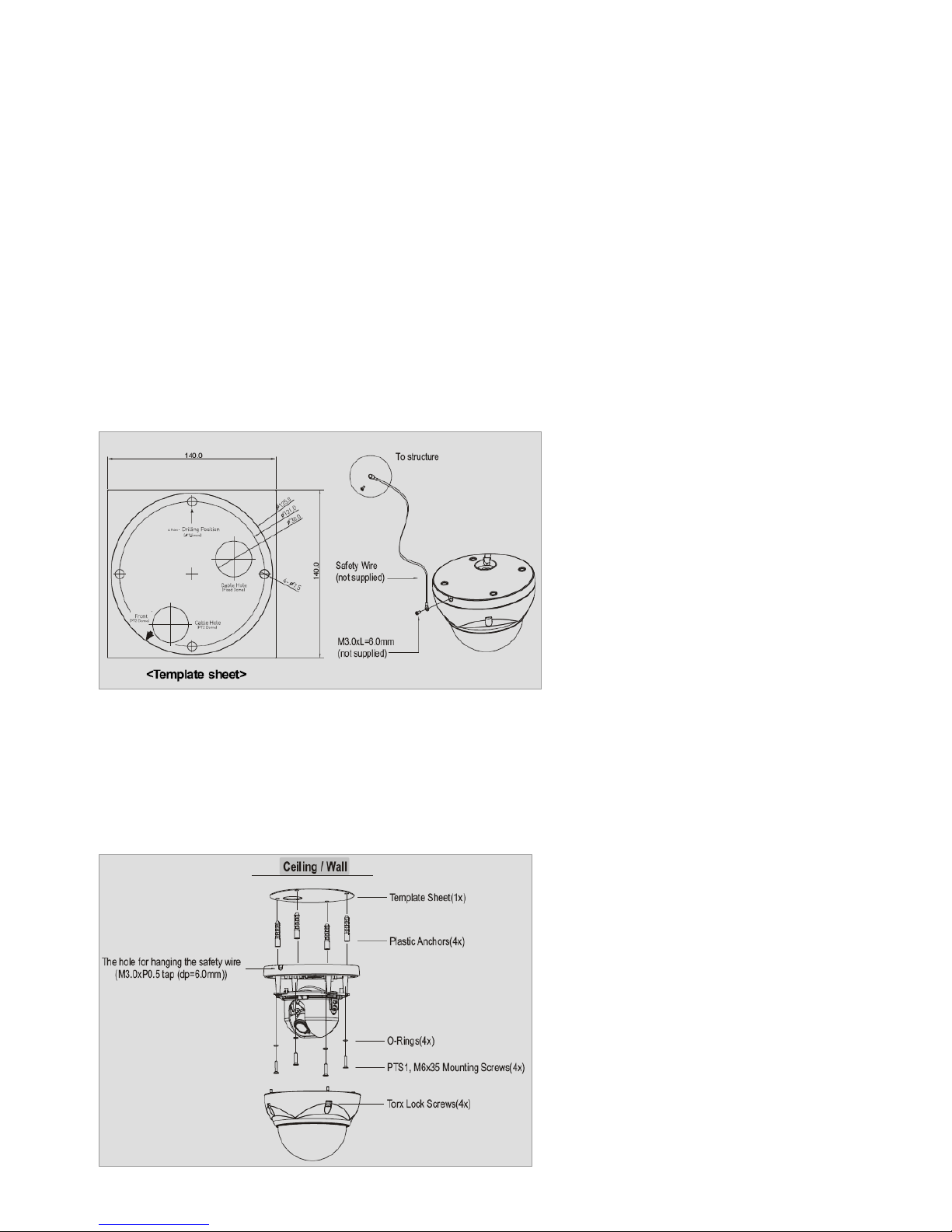
1. Make mounting holes and cable hole in the place (ceiling) to which this dome camera is installed using the supplied template sheet.
NOTE
The total mass of the main unit is approx 1.3kg. Check whether the ceiling to which the Dome Camera is installed is strong enough to
hold the unit mass. If not, the Dome Camera could fall, causing injury.
Figure 1. Mounting Hole
2. Attach the safety wire for securing the dome camera to ceiling or structure not to fall.
3. Extract each wire through the cable hole, connect BNC cable and communication lines.
4. Unlock torx screws (4x) the dome cover and fix the dome case firmly with supplied mounting screws (4x), plastic
anchors (4x), O-Rings (4x).
5. Adjust desired focus and scene by turning and moving the hemisphere by hand.
6. Lock the housing cover with torx screws (4x).
Figure 2. Lock Screw
8

NOTES
- Cable through the electrical box with the dome base
The housing can also be mounted on a 4s or 2s electrical box.
- Using the conduit knockout punched with the dome base
Remove the conduit knockout punched for the cable entry.
Figure 3. Mount electric box
Heater Kit Installation (Optional)
1. Place the heater element is sl ot “A”. Pl ease ensure that the cables are facing upwards and the heater is
pointing towards the Dome.
2. Place the PCB in slot “B”. Please ensure that the PCB is facing inside of the Dome with the connection
blocks at the top.
3. Place the plug in the Socket “C” (J3) which is found on the controller board.
Figure 4. Heater Kit Installation
NOTES
- Heater power consumption
Power Supply AC24V DC12V
Power Consumption 20Watt 10Watt
Heater On at 41°F (5°C)
Heater Off at 59°F (15°C)
- Use Certified/Listed Class 2 power source only.
9
Este manual sirve para los siguientes modelos
1
Tabla de contenidos


