Discount Fence PRX-320 Manual de usuario

PRX-320 Waterproof Proximity Access
Operating Instructions and Installation Manual


Contents
I. SPECIAL FEATURES 1
II. FRONT PANEL 1
III
V
. INSTALLATION PROCEDURES AND PROXIMITY CARD TYPES 2
IV. SETTING MODE AND FUNCTIONS 3
1. Add Proximity Card(s) 3
2. Delete Proximity Card(s) 4
3. Add / Change User Pass Code 4
4. Door Lock Time Setting 5
5. Setting Door Access Entry Mode 5
6. Batch Registration (Adding Sequential Card Series) 6
7. Anti-Tamper Output 6
8. Change System Code 7
9. Delete User Pass Codes 7
10. Delete All Proximity Cards 8
11. Door Access Using System Code 8
V. INSTALLATION OF PROXIMITY READER 9
1. Connections 9
2. Installation of electric lock and exit push button 10
3. Installation of door sensor, external relay and siren 11
I. PRECAUTIONS 12 13VII. ASSEMBLY INSTRUCTIONS
13Mounting steps 1 - 314Mounting steps 4 - 615Mounting step 716Optional Accessories

ST-320 Mode Setting
I. SPECIAL FEATURES:
1. Stand alone operation.
2. Front panel power-on indicator.
3. Four door opening modes. ENTRY MODE 1: Enter 4-digit Pass
Code only. ENTRY MODE 2: Proximity Card access only. ENTRY
MODE 3: Proximity Card plus 4-digit Pass Code. ENTRY MODE 4:
Proximity Card or 4-digit Pass Code
4. Programming Mode is protected by a 4-digit System Pass Code.
5. All Proximity Cards must be registered prior to use.
6. Maximum storage of 2000 cards.
8. Non-volatile memory protects against data loss.
II. FRONT PANEL AND PROXIMITY CARD TYPES
Indicator Lights Function
Green Status Light: Flashes to indicate panel key press. On to indicate
Programming Mode. Off in Normal Mode.
Yellow Status Light: Flashes to indicate unsuccessful access. On when
alarm is active.
Status Light Bar: Red - Power on in Normal Mode. Green – Indicates
successful access.
Ten Numeric Keys 0-9: Pass Code Entry and Programming Mode.
# Key: Confirmation Key
Clear or Escape Key
* Key:
Pg 1

Pg2
Proximity Cards
Proximity Cards will have either a single 8-digit number or an 8-digit number separated by a comma
and a 10-digit number in the center of the card. The ST-320 uses only the last 6-digits of the
8-digit number printed on either card type.
III. INSTALLATION PROCEEDURES
1 Refer to Appendix for mounting instructions.
2 Do not install Proximity Reader on or near metal objects, this will reduce the
effective range of Access Card detection.
3 Install the appropriate connector(s) to meet door access application requirements.
See the examples located on page 10 and 11.
4 Connect power to the reader.
5 The Status Light Bar should turn on Red and a single BEEP will sound. If the unit is
not attached to the mounting plate, the Yellow Status Light will be on, indicating an alarm
condition. The alarm is caused by the Anti-Tamper Switch on the rear of the unit.

IV. SETTING MODES AND FUNCTIONS **
Programming Mode Default System Pass Code: 4567 ** The system is factory preset for Entry
Mode 2 – Proximity Card Access Only. If another Entry Mode is desired, proceed to Function 5
prior to adding Proximity Cards or Pass Codes.
e on.
To enter into the Programming Mode, press the following keys in sequence:
*# 4 5 6 7 # After the last #in the sequence the system will
“Beep” once and the Green Status Light will b
The system will exit the Programming Mode automatically if no keys are pressed within 20 seconds.
The user can exit the Programming Mode any time by pressing the * key.
1. Add Proximity Card(s)
*** Placing the Proximity Card to be entered within the readers detection range instead of
entering the 6-Digit Card Code can also register single cards. This feature will only
function for individual card entry and not in the Batch Registration (Function 6) mode. Pg 3

2. Delete Proximity Card(s)
3. Add / Change User Pass Code
The System allows up to 8 different User Pass Codes to be programmed. Each Pass Code must
be a 4-digit number. The 4-digit Pass Code alone can allow door access (ENTRY MODE 1) or
be used in combination with a Proximity Card.
Pg 4

4. Door Lock Time Setting
This setting determines how long the electronic lock is active after door access. The time can be
set between 01 – 99 seconds (must use 2-digits). Set 99 seconds for toggle state (suitable for
security system).
5. Setting Door Access Entry Mode
There are four Door Access Entry Modes available in the ST-320. The unit is factory preset
for MODE 2, Proximity Card Access only.
ENTRY MODE 1: Enter 4-digit Pass Code only. (Enter 4-digit Pass
Code for door access) ENTRY MODE 2: Proximity Card access only.
(Present Proximity Card for door access) ENTRY MODE 3: Proximity
Card plus 4-digit Pass Code. (Present Proximity Card and enter 4-digit
Pass Code within 5 seconds) ENTRY MODE 4: Proximity Card or
4-digit Pass Code (Present Proximity Card or enter 4-digit Pass Code)
Pg 5

6. Batch Registration (Adding Sequential Card Series)
A sequential series of Proximity Cards can be quickly added to the system with this function.
Enter the lowest 6-digit Card Code followed by the amount of cards in the sequence. Enter
the amount of cards using a 4-digit value (75 cards = 0075)
7. Anti-Tamper Output
The system has an output dedicated to the detection of “Forced Entry” of the access door (door
contacts) and removal of the system from its mounting plate (Tamper Switch). The Function can
be set whether to include “Forced Entry” detection or not. The system Tamper Switch will always
activate the Anti-Tamper output. Enter “0” to include “Forced Entry detection. Enter “1” to
ignore.
Pg 6
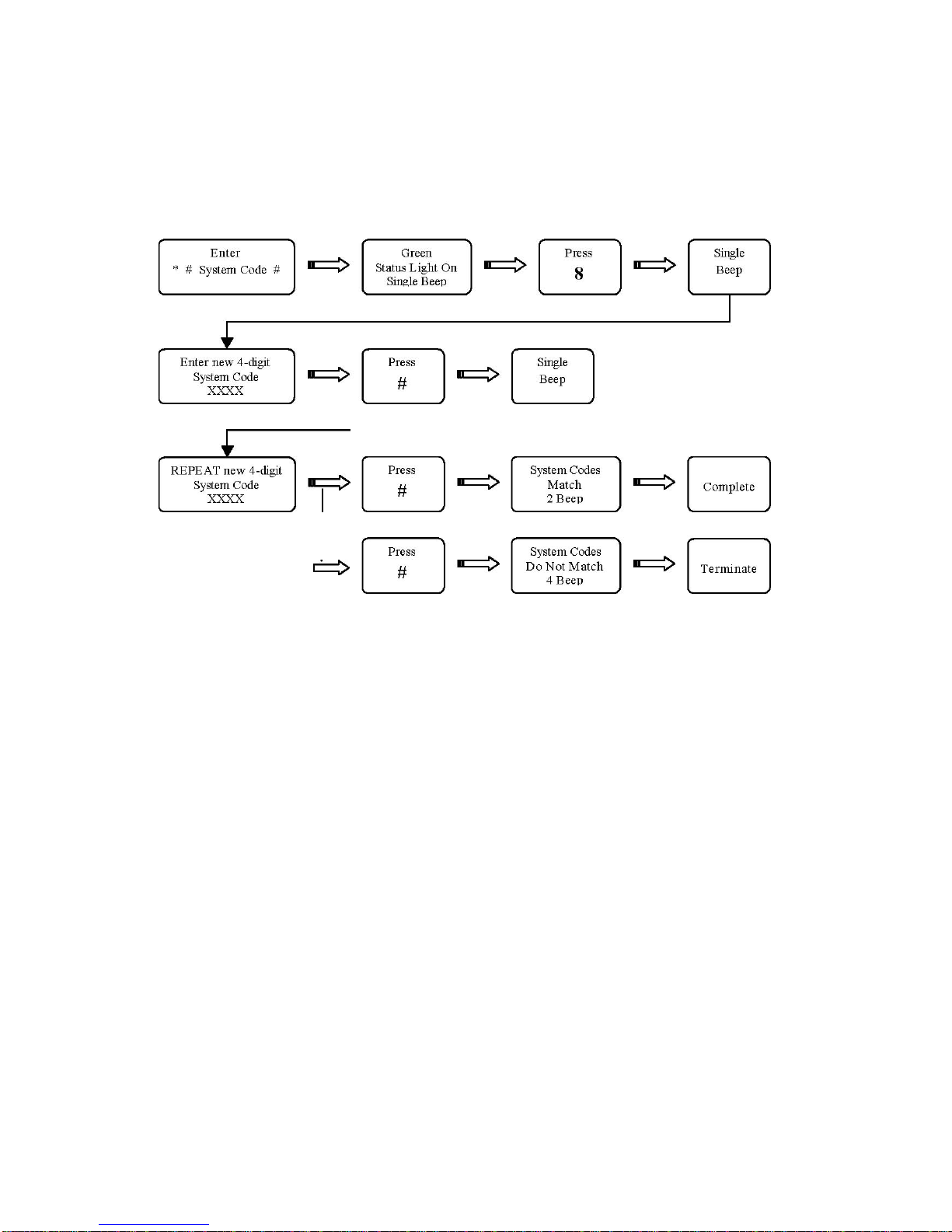
8
. Change System Code
The factory default System Pass Code: 4567 The new
4-digit Pass Code value must be entered twice.
9. Delete User Pass Codes This function will delete
ALL 8 User Pass Codes.
Tabla de contenidos


