Direct Connection RC Eclipse Manual

Page | 1
©Direct Connection RC
Eclipse Build Manual
Thank-you for your purchase of the new Eclipse kit, the following instructions are meant
to guide you in assembling your plane.
Advanced builders may find they need to make slight deviations in order to better suite
their abilities and desired plane outcome.
As always due to the type of wood used slight bends or warping to the wood may occur
but should not affect the overall structure.
**This manual contains instructions for both electric and glow type builds. **

Page | 2
©Direct Connection RC
Parts
•Leading Edge (2pcs)
•Battery Cover (3pcs)
•Fuselage bottom, left and right sides
(3pcs)
•Fin Triangles (2pcs)
•Elevons (2pcs)
•Main Spar (2pcs)
•Main Spar Brace (1pc)
•Wing tips (2pcs)
•Trailing edge; top and bottom (4pcs)
•Rib Set; Numbered 1 –7 (14pcs)
•Motor Mount (4pc)
•Center fuse former (1pc)
•Servo Tray Mount (1pc)
•Throttle Servo Mount Box Top (1pc)
•Throttle Servo Standoffs (6pcs)
•Leading edge Wing sheeting (4pcs)
•Trailing Edge Spacers (12pcs)
•Trailing edge wing tips (2pcs)
•Top wing sheeting (2pcs)
•Decals (2pcs: Graphic and logo)
Additional Requirements
•CA or Wood Glue
•CA Glue Accelerator (recommended)
•Hobby Square
•Pins
•Sanding Plane/block
•Airplane covering & necessary items to adhere
•Epoxy
Recommended Parts
•3S 2200mah Battery
•Turnigy SK3546-1400 408 watts 1500kv motor
For Glow a .15 or .25 Glow Engine
•HS85mg or HS82mg Servos
•Speed controller; 40-50amp ESC 2-4S cell
•Dubro hinges
•8x8 APC electric prop or a 9x6 Glow rated prop
•Glow Use - 120CC tank; 3 ½” x 2” x 1 ½”
•256 push rods with steel clevises and fuel line to hold the clevises closed.
•Dubro control surface horns

Page | 3
©Direct Connection RC
Pre –Build
1. Align each set of the trailing edge pieces on a flat surface along a long straight edge. Glue
together each of the trailing edge sets at the zig-zag joint using your preferred glue (CA). Allow
to set. This will leave you with a top and bottom piece for the trailing edge. Set aside.
2. Lay the two main spar pieces flat, aligning along a straight edge. Recommended keeping the slot
end up and using small weights to keep the spar as flat as possible. Glue together the two main
spar pieces at the zig-zag joint using your preferred glue (CA); allow to set. Set aside.

Page | 4
©Direct Connection RC
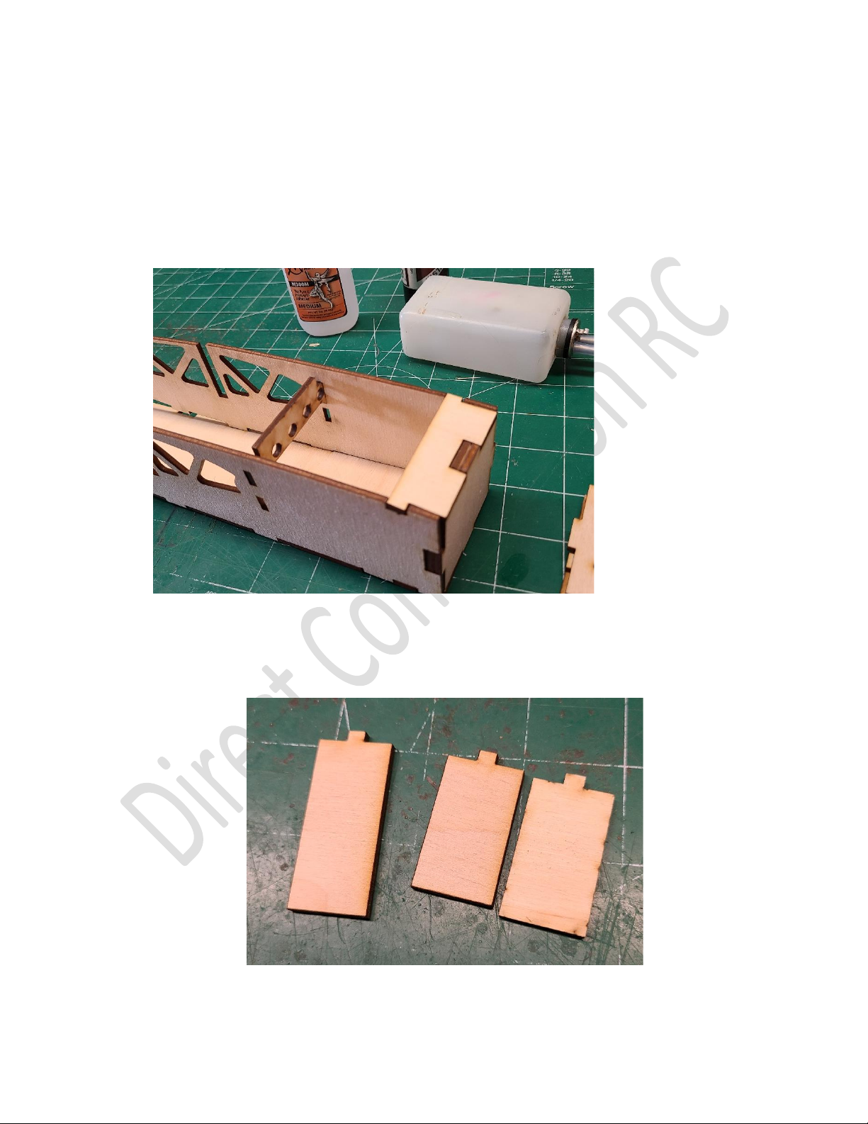
3. Assemble the 3 pieces of the battery cover. Glue and allow to set. Set aside.
4. Ensure you have a complete rib set with 2 ribs numbered 1 through 7.

Page | 5
©Direct Connection RC
Build
1. Place the fuselage bottom on a flat surface. Identify the left (top circle; longer tab) and right
(bottom circle; shorter tab) sides of the fuselage; a thrust angle is built into the fuselage.

Page | 6
©Direct Connection RC
2. Identify the two fuse formers; F1 center fuse former (electric planes) and F2 fuse former (glow
planes). Note the top and bottom of the formers as shown.
3. Option 1 Electric Plane:
Set the left and right fuselage sides upright inserting the F1 center fuse former; the F2 fuse
former is NOT required, and may be discarded. All the F1 former tabs should fit snugly inside
the fuselage. Glue the front tabs of the fuselage and the F1 former at this time. Leaving the back
portion of the fuselage open at this time.
F1
F2
Page | 7
©Direct Connection RC
Option 2 Glow Plane:
For a Glow plane discard the F1 center fuse former. Set the left and right fuselage sides upright
and insert the F2 fuse former. The F2 fuse former is designed for a 4oz (120cc) 3 ½” x 2” x 1 ½”
fuel tank application. Ensure the F2 former is aligned appropriately before gluing along with the
front tabs of the fuselage. Leaving the back portion of the fuselage open at this time.
*Ensure the fuel tank is installed BEFORE the fuselage is glued to the wing.
You will want to build your throttle servo mount box. There are 3 sets of throttle servo mount
standoffs provided depending on the height option you desire for the servo. You can run the
throttle servo linkage through the center fuse former and drill your hole in the firewall as
required for your engine throttle linkage.

Page | 8
©Direct Connection RC
Once you have selected your appropriate height, glue the standoff pieces to the top piece and
insert into the fuselage gluing into place as shown. Ensure your fuel tank is secured prior to
installing the throttle servo mount box. We recommend using foam around the fuel tank and
some kind of strap epoxied to the fuselage to hold the fuel tank in place and all other necessary
items.

Page | 9
©Direct Connection RC
4. Identify the 2 motor mount pieces depending on your airplane type; glow or electric. The pre
drilled motor mounts are designed for electric and the solid motor mount pieces are designed
for glow application. In some instances, those with electric planes may wish to use the solid
motor mount pieces when using a custom motor. The extra motor mount pieces can be
discarded or saved for future use if desired.
5. Option 1 Electric Plane:
Insert the two pre-drilled motor mounts (or customed motor mounts) these will be stacked
against one another and should be epoxied and allowed to set before installing into the
fuselage.
Option 2 Glow Plane:
Using the undrilled motor mount set Epoxy the set together and allow to set before installing
into the fuselage. Once the mounts have set, we recommend you epoxy the mount into the
fuselage prior to drilling your required holes for the engine and throttle cable. You may wish to
take this time to install your blind nuts. You may also wish to brush coat a thin layer of epoxy on
the inside of the fuselage to protect the wood from fuel leaks.

Page | 10
©Direct Connection RC
6. Install the top motor box cover onto the fuselage. We recommend Epoxy.
7. Glue in the rear servo mount tray onto the rear back portion of the fuselage.
Tabla de contenidos
Otros manuales de Juguete de Direct Connection RC


