Bluetooth® Smart Communication Interface Board
© 2016 Dialog Semiconductor
Contents
Abstract................................................................................................................................................ 1
Contents............................................................................................................................................... 2
Figures.................................................................................................................................................. 2
Tables ................................................................................................................................................... 3
1Terms and definitions................................................................................................................... 4
2References..................................................................................................................................... 4
3Introduction.................................................................................................................................... 5
4Hardware system........................................................................................................................... 5
4.1 System description................................................................................................................ 6
4.2 Cables and peripheral connections....................................................................................... 7
4.3 Switches, buttons and LEDs................................................................................................. 9
4.3.1 Reset button (SW1)............................................................................................... 9
4.3.2 Reset function........................................................................................................ 9
4.3.2.1 Target board has reset functionality.................................................. 9
4.3.2.2 Target board has no reset functionality and is powered from the
CIB..................................................................................................... 9
4.3.2.3 Target board has no reset functionality and it is not powered
from the CIB....................................................................................... 9
4.3.3 Target board power supply –ON/OFF switch (SW2).......................................... 10
4.3.4 LEDs.................................................................................................................... 10
4.3.5 Headers and jumpers.......................................................................................... 10
5Programming reference designs using CIB............................................................................. 12
5.1 Programming using JTAG mode or UART mode ............................................................... 12
5.2 Reference design configuration for programming with CIB................................................ 13
6Power consumption measurement using SmartSnippets ...................................................... 21
Revision history................................................................................................................................. 23
Figures
Figure 1: Block diagram of the CIB ....................................................................................................... 5
Figure 2: Community Interface Board –Components........................................................................... 6
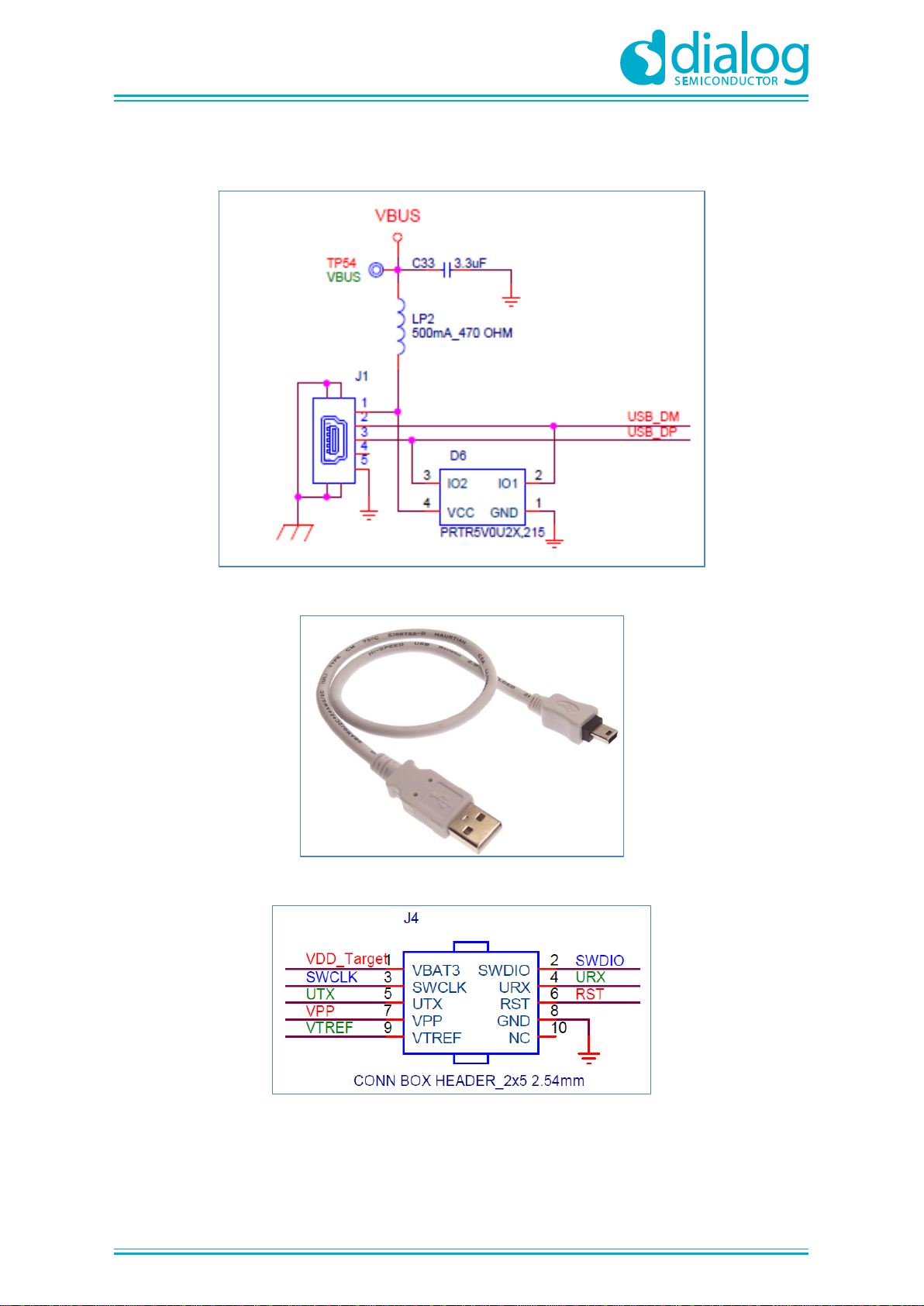
Figure 3: Schematic of the Mini-USB connector (J1)............................................................................ 7
Figure 4: The actual USB cable ............................................................................................................ 7
Figure 5: Schematic of the TAG-Connector (2.54 mm)......................................................................... 7
Figure 6: The actual TAG-Connect cable (10 pins)............................................................................... 8
Figure 7: Schematic of the IDC10 Connector (1.27 mm)...................................................................... 8
Figure 8: The actual IDC10 - 1.27 mm cable ........................................................................................ 8
Figure 9: Reset button (SW1)................................................................................................................ 9
Figure 10: Schematic of the Reset and UART/JTAG discharge circuitry............................................ 10
Figure 11: The actual Power supply switch (SW2) ............................................................................. 10
Figure 12: Headers J14, J15 and J16................................................................................................. 11
Figure 13: CIB to Target board interconnection.................................................................................. 12
Figure 14: Connecting a DA14580 Pro Motherboard to the CIB......................................................... 21
Figure 15: DA14580DEVKIT-P_vB –Header J11, pin 2 and header J5, pin 23................................. 22
Figure 16: CIB –Header J16, pins 1 and 2......................................................................................... 22