
Detex Advantex 10 Series Manual de instrucciones

Owner's Copy
P/N: 100481
101256 Page 1
Non-Roller Strike
P/N: 100234-1
Mounting plate
Subassembly
Strike Shield
P/N: 100480
Mortise Strike
Strike Shim Plastic Template
Standard
Mortise
P/N: 100088
98 Strike *, P/N: 100855-1
2" Narrow Stile
P/N: 100212
P/N: 100311-X (Narrow)
Centercase Cover
P/N: 100196-X (Wide)
99 Strike *, P/N: 100855-2
P/N: 100482 P/N: 101899
Strike Shim Plastic Template
- Glass Bead Kit
- Sex Nuts
- Tamper Kit
- Double Door Strike Kit
- Key Stop Kit
Hex Nut
P/N: 100783
Hex Key
P/N: 100450
See
Optional Accessories
For:
Detex Corporation, 302 Detex Drive, New Braunfels, Texas 78130-3045
(830)629-2900 / 1-800-729-3839 / Fax (830)620-6711
E-MAIL: detex@detex.com INTERNET: www.detex.com
INSTALLATION INSTRUCTIONS FOR DETEX ADVANTEX® RIM 10/40 SERIES, F10/F40 SERIES
AND "H" MODELS (HURRICANE)
U.S. PATENT NUMBERS:
6009732
6205825B1
6532777B2
INTERNATIONAL PATENT NUMBER:
PCT6009732
Fillerplate Subassembly (LD)
Use for ease of installation
Plastic Template
Centercase/Pushpad SubAssembly
P/N: 101642-X
Endcap
P/N: 100147
P/N: 101093
Endcap Bracket
RIM
Endcap Bracket with
9V battery holder
Fillerplate
SubAssembly
Mounting plate
Subassembly
(narrow stile)
P/N: 100696-1
Mounting plate
Subassembly
(wide stile)
P/N: 100697-X
101256 April 20, 2007
P/N: 100860-3
Fillerplate SubAssembly (EA x CD)
Fillerplate SubAssembly (CD)
P/N: 100860-1
Fillerplate SubAssembly (HD)
P/N: 100860-4
P/N: 100860-2
9V Battery
P/N: PP-5567
P/N: 100783
Hex Nut
Mortise cylinder not included with device.
Standard Yale type cam required.
* Note: Parts listed above will vary
according to product configuration.
Door Sign
P/N: EA-561
(electrified versions only)
®
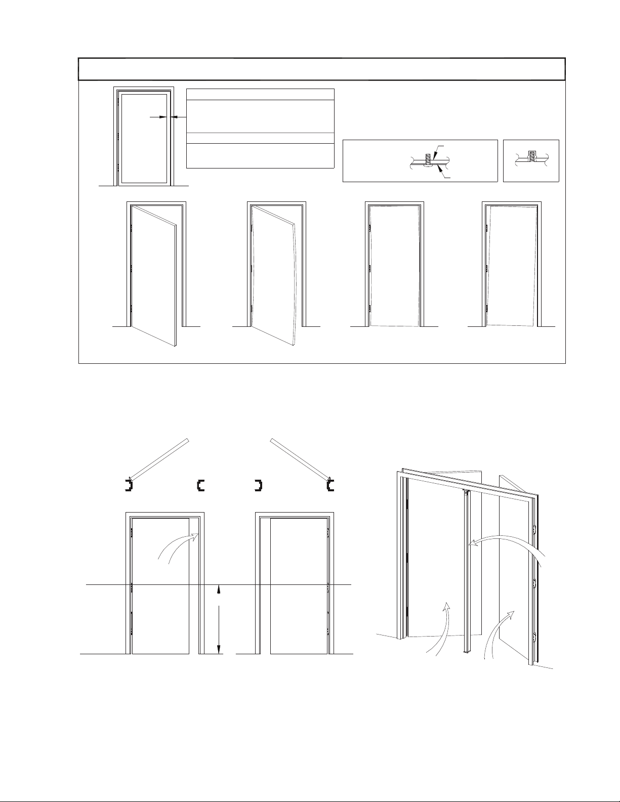
Door Must Not be Warped
LHR Door
101256 Page 2
NOTE: 750mm MAXIMUM DOOR WIDTH OPENING FOR EUROPE FOR 36" DEVICE
1000mm MAXIMUM DOOR WIDTH OPENING FOR EUROPE FOR 48" DEVICE
THE SAFETY FEATURES OF THIS PRODUCT ARE ESSENTIAL TO IT'S COMPLIANCE WITH EN 1125.
NO MODIFICATION OF ANY KIND, OTHER THAN THOSE DESCRIBED IN THESE INSTRUCTIONS ARE PERMITTED.
L
C
Floor
Finished
Stop Face
Reference
Horizontal
40"
Door Must Swing Freely
RHR Door
LHR Door
Inside Face
RHR Door
Inside Face
Face
Mullion
Door Must Not Sag
Door Must Not Bind
Template drawings provide door and frame
structural and dimensional specifications for
!!!CHECK BEFORE STARTING!!!
Mortise strike recommended
Minimum door stile 2" (51mm)
door and frame preparation.
Narrow Stile
Surface strike possible
X
Wide Stile (Surface Strike)
Minimum door stile 4-1/2" (114 mm)
Unreinforced Doors: Use Sex Nuts and Bolts
X
Blind Rivet Nut
Reinforcement
Door Skin
threads.
least (3) screw
frame engages at
Reinforced door or
X
Fasteners for unreinforced openings are not supplied by Detex.
Unreinforced Frames: Use Blind Rivet Nuts (see sketch)
Doors and frames with walls having a structural thickness (metal skin
screw threads, are considered unreinforced for hardware.
plus reinforcement, or solid wood) to engage less than (3) full
X
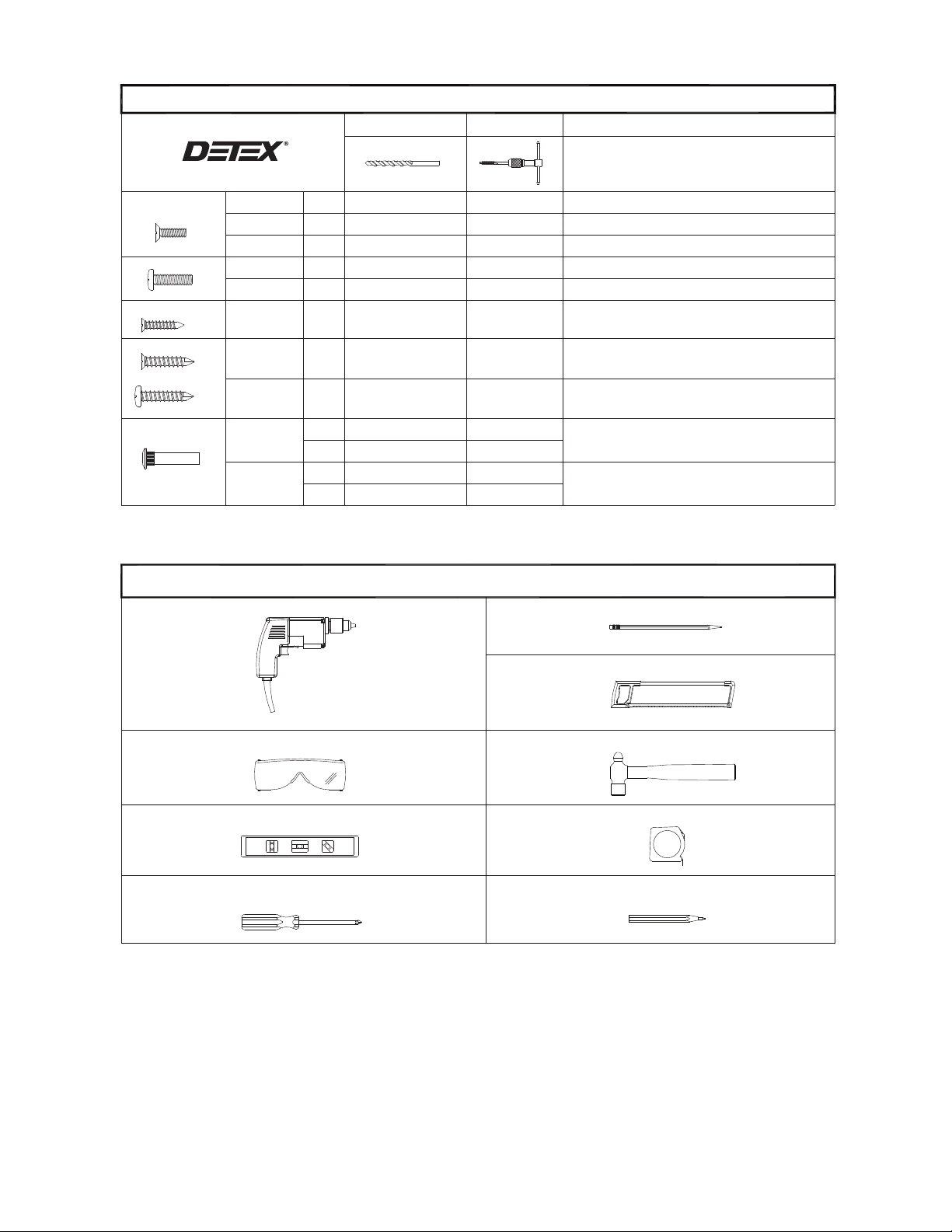
Level
Screw Driver
#10-32
----
----
Power Drill
(2) Mortise Cylinder NOT Provided.
Safety Glasses
#6-32 x 3/8"
#1/4-20 x 1"
#1/4-20 x 1/4"
#10-24 x 5/8"
#6-32 x 5/8"
Machine Screws
#1/4-20
----
Sex Nut
----- Used on Mounting plate and Endcap Mounting Holes
3/8" Exterior Door Face
Center Punch
Tape Measure
101256 Page 3
Used on Strike Hook Mounting Holes
Unreinforced Hollow Metal Doors
Recommended on Fire Rated Wood and
Hack Saw
Pencil
-----
-----
Hammer
13/64" Interior Door Face
5/16" Exterior Door Face
Tools Required
Used on 99 Strike Center Mounting Hole
Used to Mount Centercase Cover and Endcap
Use Either Machine Screws, Sheetmetal Screws,
Used on 98 Strike Shield Mounting Holes
Used on Strike, Mounting plate, and Endcap Mounting Holes
Used to Fasten Centercase Unit onto Mounting plate
Unreinforced Hollow Metal Doors
Recommended on Fire Rated Wood and
#10-24 Tap
-----
-----
#6-32 Tap
#25 or 9/64"
#7 or 13/64"
-----
-----
#36 or 7/64
#1/4-20 Tap
-----
9/32" Interior Door Face
or Sex Nuts
Drill Bit
Fastener Table
Tap Wrench Comments
#14 x 1" PPH
Sheetmetal Screws
#10 x 1"
#6 x 1"
PFH
PFH
Used on Strike, Mounting plate, and Endcap Mounting Holes
NOT REQUIRED ----- Metal Applications
9/64"
NOT REQUIRED -----
-----
Used on 99 Strike Center Mounting Hole
Used on 98 Strike Shield Mounting Holes
PFH
PFH
PFH
Self-drilling Screws
PPH
PPH
Note: (1) Fastener selection will vary per catalog configuration and kits ordered.
----

self-drilling screws
1/4-20x1" machine
screws or #14
lockwashers and
Fasten tightly with
101256 Page 4
6
self-drilling screws
screws or #14
Fasten loosely with
two 1/4-20x1" machine
for unit
40 inches above
finished floor
Mark centerline
1
label temporarily
and strike hook installation)
(see appendix C for 98 strike
into mounting plate
Slide 99 strike locator
Mounting plate Hole
Strike holes
holes
4
to mark trim hole
Punch marked
Mark mounting plate
and strike holes
2
Mounting plate
hole
3
If necessary, remove
Mounting plate holes (2)
For 1/4-20 machine screws drill #7 holes.
For #14 self-drilling screws no pilot holes
necessary.
For sex nuts drill 3/8" holes.
(see fastener table)
Strike holes (2)
For 1/4-20 machine screws
drill #7 holes
No pilot hole necessary
for #14 self-drilling screws
(see fastener table)
if necessary.
(see outside
trim instructions)
Trim input hole
5
RECOMMENDED

with 1/4-20 x 1/4" PPH
machine screws
Fasten rim device
to mounting plate
101256 Page 5
2
MUST BE INSTALLED!
Position cam as shown
Insert centercase into slots
of centercase mounting plate,
depress pushpad, rotate
toward door.
1
DOOR

Install battery in endcap
and connect.
3Endcap
(top view)
For maximum cut down,
this portion of center tab
may be cut off
101256 Page 6
Secure with tape Protect wires
door frame clearance.
Check for device and
proceed to the next step.
1
If no cut-off needed,
CAUTION:
*
during cutting 2
L
Cut fillerplate
desired length
and extrusion to
(Cut-Off procedure if required)
onto extrusion
Slide endcap assembly
Type 48" Unit
Standard Cut-Off*
2 in
36" Unit
8 in
Length (L)
LD 6-1/2 in 12-1/2 in
HD/CD 4-3/4 in. 10-3/4 in
with
Reassemble electronics
beyond edge of cut fillerplate.
Electronics may extend
after cutting.
3
during cutting
Protect wires
4
tape
Cut fillerplate & extrusion to
desired length*
Procedures for Maximum Cut Down Lengths
1
Caution Required-Special Handling
(Call factory at (800) 729-3839 for assistance)
prior to cut down
REMOVE electronics
Secure
2prior to cutting
FLUSH to extrusion
Align fillerplate
Type
6 1/2 in
5-1/2 in.
36" Unit
HD/CD
LD
Electrified Model
12 1/2 in
11-1/2 in
9 in
48" Unit
3 in
Max Cut-Off
Length (L)
Electrified Model
call factory at (800) 729-3839
for assistance.
For additional cut down lengths,
NOTE:
CHECKING FOR DEVICE CLEARANCE
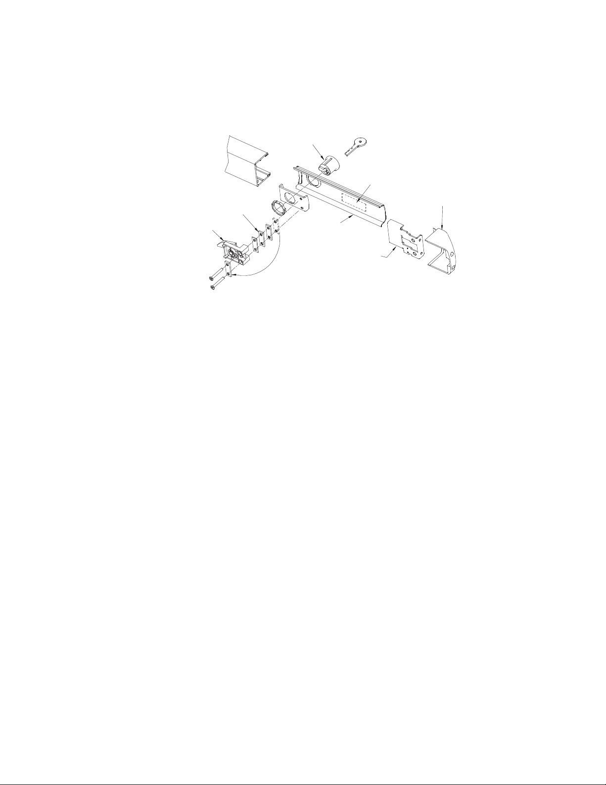
Fillerplate
CD shown (EA Similar)
Dogging
Assembly
Spacers
Cylinder Installation
Endcap
Endcap
Mounting
Bracket
Wiring Label
(EA only)
Follow steps "a" through "e" for both CD and EA cylinder installations
CD (Cylinder Dogging) and EA (Exit Alarm)
MORTISE CYLINDER INSTALLATION
Mortise
Cylinder
a. Remove endcap and endcap mounting bracket.
Figure A1
b. Remove fillerplate. Caution: EA models have electronic components susceptible to damage.
e. Trial fit dogging assembly. If cylinder is too short, remove spacers as necessary and reattach them under
the (2) screw heads (See Figure A1). Fasten the (2) screws to the rest of the assembly.
d. Install mortise cylinder (sold separately) with large hex nut provided.
c. Remove and discard shipping insert and nut. Loosen (2) screws from dogging assembly.
101256 Page 7
f. Rotate key counterclockwise
CD installation
g. Assembly complete. Continue with Panic Hardware instruction.
Caution: The key should easily turn in both directions.

self-drilling screws
Fasten rim device
to mounting plate
and door with
1/4-20x1" machine
screws or #14
For 1/4-20 machine screws drill #7 holes.
For #14 self-drilling screws no pilot holes
necessary.
For sex bolts drill 3/8" holes.
Align the 99 strike with the
latchbolt.
Firmly tighten screws
(shim if necessary)
Slide endcap bracket into
extrusion, level pushpad assembly,
and mark (2) holes
Note: Endcap bracket must bottom-out
on extrusion before marking holes.
holes
Punch marked
4
12
Install (2) 10-32 FH Screws
IMPORTANT:
to attach Endcap
to endcap bracket
Slide and mount endcap
5
101256 Page 8
9
Install cover with 6-32
machine screws. Tighten
with hand tools only.
3
8
6
Note:
Check device function and
marking and drilling for
center screw.
strike engagement BEFORE
Mark and drill center hole.
9/64" for 10-24 machine screws.
(see fastener table)
No pliot hole necessary for
#10 self-drilling screw.
Secure the 99 strike.
7
Deadlatch
99 strike
MANDITORY FOR HURRICANE MODELS
EMERGENCY EXIT ONLY
ALARM WILL SOUND
Place EA-561 sign on door
(For Electrified Models ONLY)

Off *
Auto rearm
On
On *
Disable
Low Battery
On
Off *
Disable
Off
Indicator
Status
Table 3
See Table 1
STATUS INDICATOR switch set to "OFF"
Disable AUTO REARM switch set to "ON"
* Factory default settings:
See
Table 2
Table 2
Table 3
Dis Lo Bat
Disable
ON
ON
STATUS
ON
INDICATOR AUTO REARM
Selector switches detail
See
EA SWITCH OPTIONS
Table 1
Figure 1
Extended bypass is enabled.
The Device flashes red or green LED every 15 seconds.
The Device gives no indication of armed or disarmed status.
Red indicates armed status and green indicates disarmed.
Auto Rearming Feature Setting
Alarm sounds until turned off with key.
Status Description
Switch selections must be made before applying power or installing battery (See Figure 1)
Note: AC power must be applied for switch to operate
The device flashes one red LED and one beep about every 45 seconds
The device gives no indication of battery being low.
Status Description
Alarm will automatically rearm after 2 minutes.
Unit sounds alarm for 2 minutes after bar is released.
P1
J1
EA wiring detail
Figure 2
N.O. contact
101256 Page 9
N.O. contact
Violet
----
Violet 1
2
3
----
Pin 5
Pin 6
Pin 4
Remote Bypass
Figure 3
P1 detail
4
5
6
Protect wires to avoid pinching
Dis Lo Bat switch set to "OFF"
(Standard)
Contacts rated at 1.0A @ 30VDC or 0.5A @ 125VAC
Battery Connector
(P1 wire usage)
Table 4
Remote Signal
Pin 2
Pin 3
Pin 1
Yellow
Green
Normally Open
Normally Closed
Common
Brown
(EA shown)
Bypass/Remote Signal
(Optional)
P2
12V AC/DC External Supply
(24V AC/DC Optional)
J2
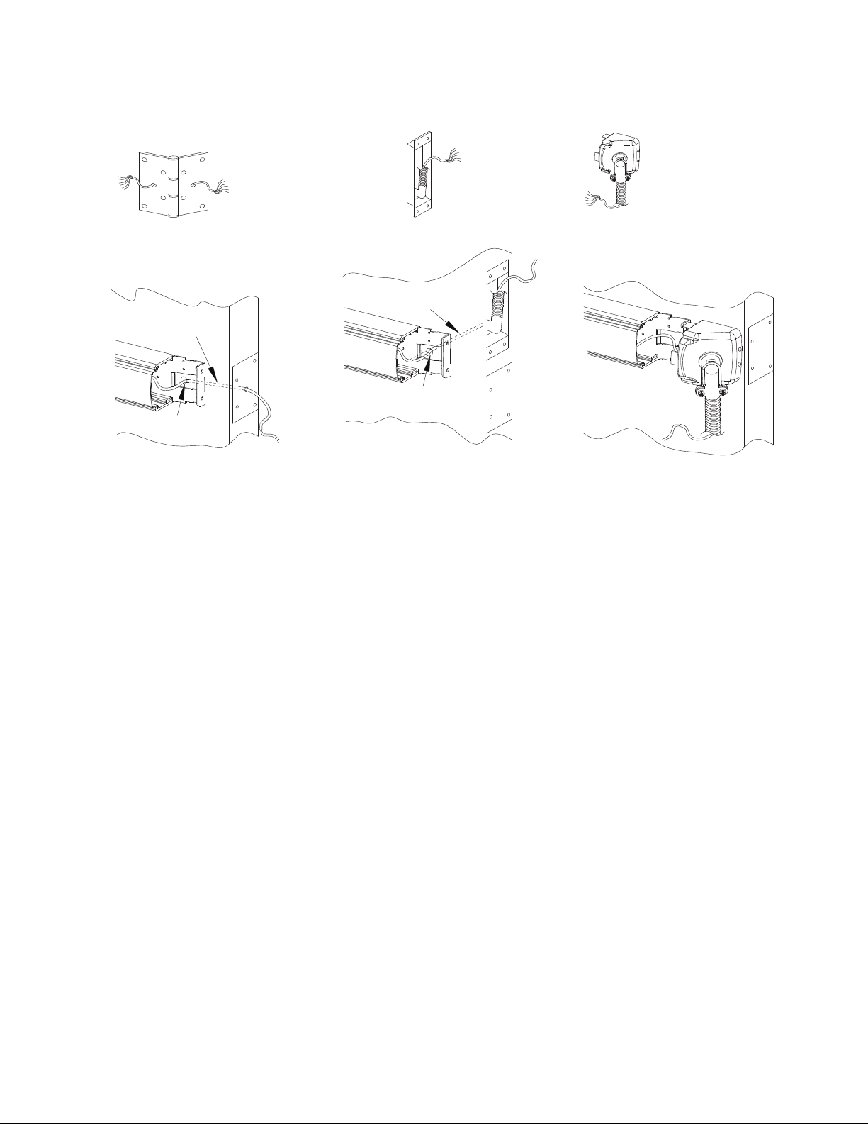
Flex Conduit/End Cap Kit
p/n: FCA
(Order FCA x Finish)
FCA Flex Conduit Endcap Prep
Note: For high traffic areas an electric through-wire hinge or power transfer is recommended.
101256 Page 10
Wire chase through door
HARDWIRE TRANSFER DETAIL
(Requirements: Minimum 6 Conductor Wires, Maximum 12 Conductor Wires)
Power Transfer Endcap Prep
Electric Hinge Endcap Prep
1/2" Hole through the
inside door face
Wire chase through door
Electric Hinge
p/n: EWH8-X
1/2" Hole through the
inside door face
Power Transfer
p/n: PT-5
Otros manuales para Advantex 10 Series
1
Este manual sirve para los siguientes modelos
4
Tabla de contenidos
Otros manuales de Cerradura de puerta de Detex

Detex
Detex ADVANTEX 87 Series Manual de usuario

Detex
Detex ADVANTEX 82 Series Manual de usuario

Detex
Detex EAX-500 Manual de usuario

Detex
Detex ADVANTEX 62 Series Manual de usuario

Detex
Detex ADVANTEX 30 Series Manual de usuario

Detex
Detex ADVANTEX 80 Series Manual de usuario

Detex
Detex ECL-620 Manual de usuario

Detex
Detex ADVANTEX 60 Series Manual de usuario

Detex
Detex ADVANTEX 70 Series Manual de usuario


