Delta M815-MX Series Manual de usuario

CopyrightNotices
The information contained in the user’s manual and all accompanyied
documentation are copyrighted and all rights are reserved. This publica-
tion may not in whole or in parts, be reproduced, transcribed, stored in a
retrieval system translated into any languages or transmitted in any form
without the prior written consent from the manufacturer, except for copies
retained by the purchasers for their personal archival purposes.
Trademarks
Award Modular BIOS is a registered trademark of Award Software Inc.
Microsoft and Windows 95/98/NT are registered trademarks of Microsoft
Corporation.
Intel Pentium, Pentium II, Pentium III, Celeron and Slot1 are registered
trademarks of Intel Corporation.
All other product names mentioned herein are used for identification pur-
poses only and may be the trademarks of their respective companies.
Technical Support
If you need technical assistance, our technical support engineers will be
glad to assist you with all technical difficulties, you can reach them by
dialing our toll-free service and technical support number : 1-877-DELTA-
2K/1-877-335-8225 (USA/CANADA Only ). Not only you will get to speak
with our experience technical support team, we also provide web-site
address (http://pc.delta.com.tw), product ,sales and RMA/warranty
information. Our skillful technical engineers will be available between 8:
00AM to 5:00PM, PST (Pacific Standard Time).
PRINTEDINTAIWAN

Table of Contents
1. Introduction...........................................................................3
Checklist...............................................................................3
Hardware Specifications and Features....................................4
2. Hardware Installation.............................................................6
Installation Steps....................................................................6
Motherboard Layout Map.......................................................7
Pre-Installation Procedure......................................................9
Install the Motherboard in a Case..........................................19
3. BIOS Setup Utility.................................................................31
Standard CMOS Features......................................................32
Advanced BIOS Features......................................................35
Advanced Chipset Features..................................................38
Integrated Peripherals...........................................................41
Power Management Setup.....................................................45
PnP/PCI Configurations......................................................48
PC Health Status...................................................................49
Frequency Control.................................................................50
Load Fail-Safe/Optimized Defaults.......................................51
Set Supervisor/User Password...........................................52
Save & Exit Setup/Exit Without Saving.................................53
4. Installing the Utilities............................................................55
DELTAHardWare Doctor 3.60 For Win9X Installation...............56
Intel 815(E) VGA Installation...................................................57
Intel 815(E) INF Installation.................................................58
Intel 815(E)ATA66 Installation.................................................59
Audio Driver For 815(E) Installation.......................................60
BIOS Utility.......................................................................61
P/N:5011504001 JULY/2000 REV1.1
M815-MX Series User’s Manual 3
This chapter provides information that you should be familiar with before using the
system. It includes checklist and specification of the motherbaord.
Checklist
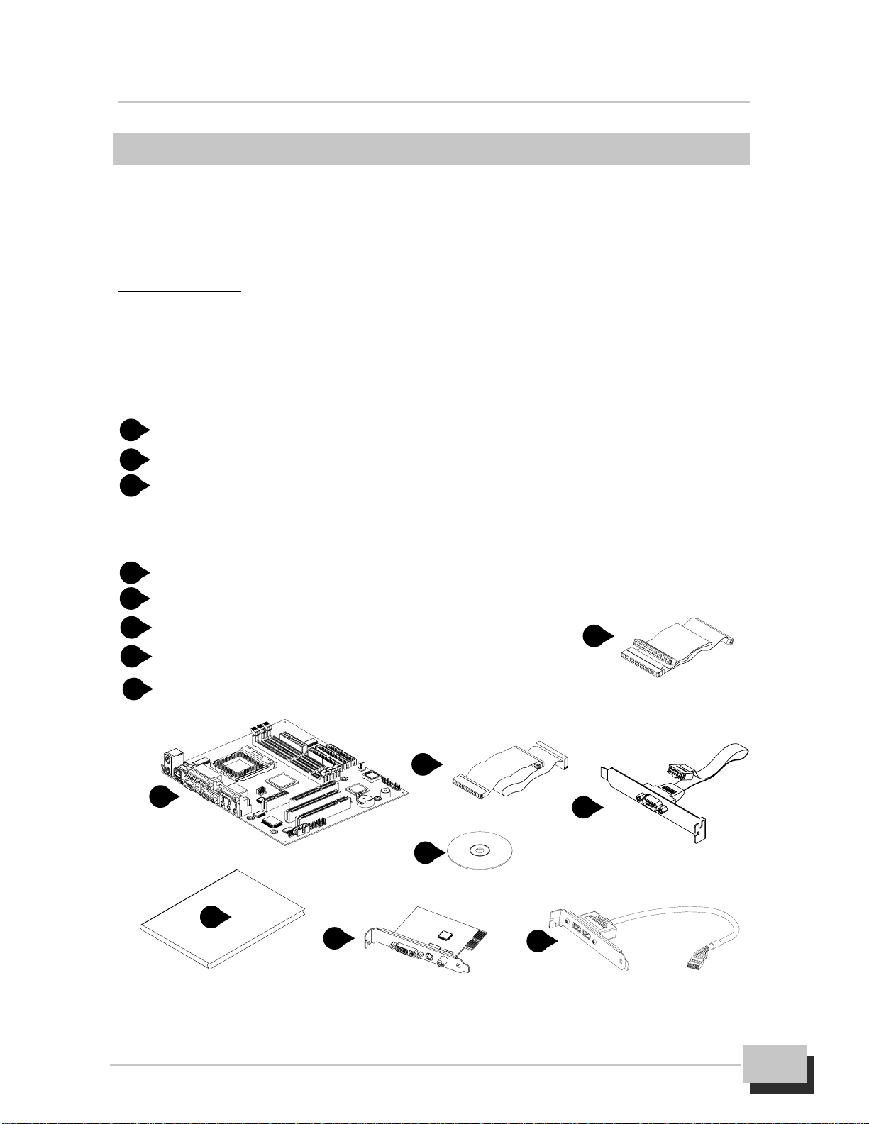
Thankyou for choosingthesystem. The packageboxcontains the followingcontents.
After unpacking, make sure that you have everything and that individual components
are not damaged. If you find any component missing or damaged, contact your
retailer immediately.
M815-MX series Motherboard
FDD Ribbon Cable Assembly
IDE Ribbon Cable Assembly
The 80-Pin ribbon cable is designed with 40-Pin connector for UltraDMA33/
66 IDE device.
Auxiliary Serial Cable Assembly with Bracket
User’s Manual
Driver and Utility CD-ROM
DVI/TV-OUT Riser Card (Optional)
Auxiliary USB Cable Assembly with Bracket (Optional)
Items 7,8 is optional at the time of purchase that you can ignore
it on checklist.
1. Introduction 1. Introduction
1
2
3
4
5
6
7
8
14
2
3
5
6
78

M815-MX Series User’s Manual
4
Hardware Specifications and Features
Chipset
M815-MX series motherboard consists of the Intel 815 chipset Graphics
and Memory Controller Hub (GMCH into a single 544-Pin BGA package),
the I/O Controller Hub (ICH into a single 241-Pin mBGA package), and the
Firmware Hub (FWH into a single 32-Pin PLCC package).
Winbond W83627HF-AW LPC Super I/O chipset
Digital link sound with AC’97 Codec onboard
CPU Support
Intel PPGA/FC-PGA Celeron and FC-PGA Pentium III series processors
System Speed Support
66/100/133MHz FSB for CPU Interface
33MHz PCI Bus for PCI Interface
66MHz AGP Bus for AGP Interface (either via a connector or a slot on the
motherboard)
100MHz (PC-100)/133MHz (PC-133) SDRAM Bus for Memory Interface
Memory
64-bit Advanced Memory Controller supporting PC-100/PC-133 SDRAM,
memory types.
Support 3 DIMMs socket, 168-Pin, 3.3V unbuffered for up to 512MB of
DRAM (128MB DRAM technology).
Integrated Local Graphics Memory Controller supporting 133MHz memory
clock for up to 4MB of display cache
Expansion Slots Support
Two 32-bit PCI master slots with v2.2 compliant
One 32-bit AGP (2X/4X) slot with v2.0 compliant (Supporting graphics
adapter or AIMM card)
One AMR slot (Supporting AMR or DVI/TV-OUT function via a riser card)
System I/O Support
Two PCI Bus master IDE-channels support UltraATA33/66 up to

M815-MX Series User’s Manual 5
1. Introduction
66MB/s DTR and one FDD port
Two DB-9 16550 UART serial port (If you want to have auxiliary serial port
available in your system, you must install the serial cable assembly which
is supplied with this motherboard), and one DB-25 ECP/EPP parallel port
Five USB ports with v1.1 compliant (If you want to have auxiliary USB ports
available in your system, you must purchased the USB cable assembly
from sales agent)
One mini DIN-6 PS/2 mouse and one mini DIN-6 PS/2 keyboard port
One IR (Infrared) I/O compliant connector (Optional)
One standard DB-15 analog VGA port
One game/MIDI port and three audio jacks (Line-out, Line-in, Microphone)
BIOS Support
Award Plug and Play flash BIOS,Soft power-down and Suspend-to-DRAM
PCI (v2.2), APM (v1.1), DMI (v2.0), SM (v2.3), ACPI compliant
Smart BIOS ROM protect function
Power recovery after interrupt feature
Extend Feature Support
Hardware monitoring temperature, supply voltages and fan speed
System power on by PS/2 keyboard and mouse
Modem Ring-On and Wake-up On LAN function
Power
Harris HIP6021 PWM power controller
ATX Power Supply configuration
Utilizes GTL+bus to reduce power consumption and EMI
Compliancies
FCC compliant and CE certification
Form Factor
MicroATX 9.60” (L) x 8.27”(W) x 4 layers PCB
Environment
Operating Temperature : 0 ~ 500C
Operating Humidity : 10 ~ 80%RH
Vibration : 0 ~ 500Hz

M815-MX Series User’s Manual
6
This chapter provides information that you should be familiar with before install the
system. It describes how to install on a step-by-step guide and explains how to use
your motherboard to build a powerful system.
Installation Steps
Before install your system. You must complete the steps:
Check Motherboard Jumper Settings
Install CPU and Heatsink/Cooling Fan
Install SDRAM Memory Module
Mounting the Motherboard in the Chassis
Connect IDE, CD-ROM Drives and Ribbon Cables
Install Add-on Card
Connect Panel Wires and Power Supply
Connect PS/2, USB, Serial, Parallel and Others Devices
Setup the BIOS Configuration and Utility Software
You are now ready to install your system, the first thing you should do is ready this
user’s manual. It contains important information which will make configuration and
setup much easier. Here are some precautions you should follow when installing
and selecting side for the system.
Store the provided accessories in a designated place for your
convenience. You will need them to install an optional device or trouble
shoot the system, as well as to set it up.
2. Hardware Installation
2. Hardware Installation
M815-MX Series User’s Manual 7
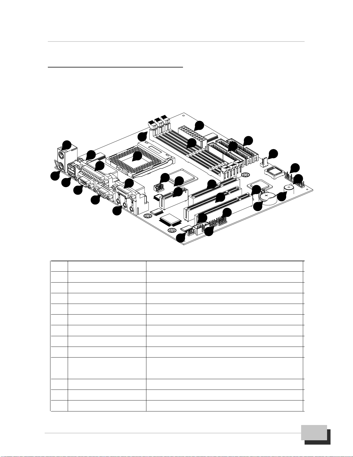
No. Location Function
1 K/B & MS (Upper) PS/2Mouseport
2 K/B & MS (Lower) PS/2 Keyboardport
3 USB1 USBports
4 LPT1 (Upper) Parallelport
5 COM1 Serialport
6 VGA1 VGAdisplayport
7 GAME_AUDIO(Upper) Game/MIDIport
8 GAME_AUDIO(Lower) Threeaudiojacks,(Line-out,Line-in, Microphone)
9 J2, 3 (CD-IN) Analogaudioconnectorforsoundoutputfrom
CD-ROM/DVD drives
10 JP2 JumpertosetAMRorDVI/TV-OUTfunction
11 AMR1 OneAMR(AudioModemRiser)slot
12 AGP1 OneAGPslotforAGP(2X/4X)graphicsadapter
1
23
14
23
4
5
6
8
7910
11 12
13
17
16
18
19
20
25 24
26
27
29
28
30
22
15
21
Motherboard Layout Map
Use the following illustration and key to identify the major components on the
motherboard.

M815-MX Series User’s Manual
8
13 PCI1, 2 Two32-bitPCIexpansionslots
14 J9(WOL) Wake-upOnLANconnector
15 COM2 Connectorforauxiliary serialCOM2port
16 J10 (IrDA) Infraredconnector(Optional)
17 J11,12(USB2) AuxiliaryUSBconnector (Optional)
18 BAT1 LithiumCR2032battery
19 BZ1 Warningandjudgingthesystemstatebybuzzer
20 LED(PWRLED) PowerLEDformonitoringpowerstate
21 FSP1 Connectorsforpanelswitchesandindicators
22 JP3 JumpertosetCMOSstate
23 J8 (CHASSIS FAN) Fanconnectorforchassiscoolingfan
24 FDC1 Floppydiskdrive connector
25 IDE1,2 Primary/SecondaryIDEchannelconnector
26 ATX1 ConnectorfortheATXpower supplycable
27 DIMM1, 2, 3 DIMMsocket forSDRAMmemorymodule
28 J1(CPU FAN) FanconnectorforCPUcoolingfan
29 PGA370 CPUsocketforPGA370processors
30 JP1 Jumpertosetkeyboard ormousepoweron
Infrared function are optional at the time of purchase that you can
ignore it.
Ground yourself properly before removing your any devices from the
anti static bag. To protect them against damage from static electricity.
Unplug the power from your system and then touch any metal part on
the system chassis.
Avoid touching device components, such as IC chips, leads, and
connectors. Hold the device by its edges and do not touch the bottom
of the board.
Place components on a grounded anti static pad or on the bag that
came with the component whenever the components are separated
from the system.
Do not place the system in the following locations. It may cause mal
functions of the system.

2. Hardware Installation
M815-MX Series User’s Manual 9
Locations with sudden changes in temperature. A sudden change
in temperature causes condensation to form, which could result in
failures of the system.
Locations with strong vibration, Failure to follow this warning may
cause not only malfunctions of the system but personal injury or
property damage to the surroundings.
Do not use a power outlet that shares the ground line with another
(especially the one to which a device with large power consump
tion is connected) for the system.
Pre-Installation Procedure
Before you install your motherboard into a chassis, it’s convenient to install the CPU,
install the memory modules, and set all the jumpers to correct settings.
Jumpers Setting Explain
This motherboard has jumpers that need to be set correctly. You can use a jumper
cap to connect two adjacent pins. When a jumper cap connects two pins, we say
that the pin are SHORT. If you remove a jumper cap from two pins (or placed on just
a single pin), we say that the pin are OPEN. The examples and illustrations below
show the different positions of a jumper cap on the typical 3-Pin jumper. By changing
the jumper cap, you change the circuit of the motherboard and enable or disable
certain feature or properties of the board.
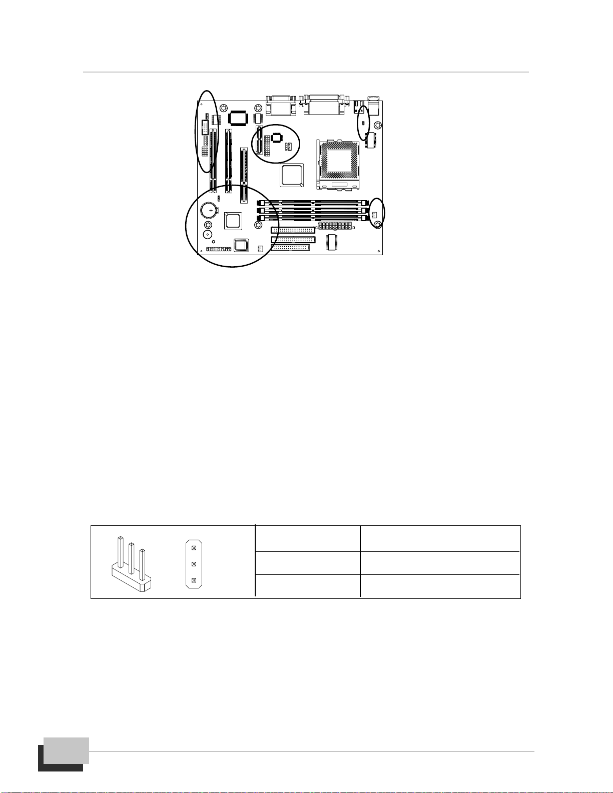
Locate the Jumpers on the Motherboard
3-Pin jumper with a
singlejumpercap 3-Pin jumper with
pins1-2SHORT 3-Pin jumper with
pins2-3SHORT
M815-MX Series User’s Manual
10
JP3: Clear CMOS Memory Jumper
Use this jumper to clear the contents of the CMOS memory. The setup utility is
stored in CMOS, so you might need to clear this memory if incorrect setup data is
stopping your system from starting, or your system can not boot-up because you
forgotpasswordandthesystemBIOShasbeenupdated.Pleasefollowinginstructions
can be performed to clear CMOS memory.
Disconnect the ATX power supply cable from the motherboard, then move the
jumper cap to short Pins 2-3 of JP3 for 3-5 seconds.
Return the jumper cap to Pins 1-2 (normal setting) of JP3.
Reconnect the power supply cable and turn on your system power. Then
access BIOS setup, please refer to the BIOS configuration application.
JP1: PS/2 Keyboard/Mouse Power On Jumper
System power can be turned on by a PS/2 keyboard or a PS/2 mouse. To enable the
Power On by PS/2 keyboard or mouse feature, you need to short JP1 pin1-2 and set
“Power On Function” in “Integrated Peripherals” setup accordingly. See chapter 3
BIOS setup for more information.
Jumper Setting Function
SHORT Pins 1-2 NormalOperation
SHORT Pins 2-3 ClearCMOS
1
3
Tabla de contenidos
Otros manuales de Placa madre de Delta


Manuales populares de Placa madre de otras marcas


Telit Wireless Solutions
Telit Wireless Solutions SL869-3DR Manual de usuario

Gigabyte
Gigabyte GA-9IVDT Manual de usuario

Texas Instruments
Texas Instruments ADS8372EVM Manual de usuario

Commell
Commell MS-C73 Manual de usuario

IBT Technologies
IBT Technologies MB860 Manual de usuario

Nvidia
Nvidia TEGRA DG-04927-001_V01 Manual de usuario


