Deka SPACESAVER Interlock AVR45 Manual de usuario

Proposition
65
Warning:
Battery posts, terminals and related accessories contain lead and lead compounds, chemicals known to the
State of California to cause cancer and reproductive harm. Batteries also contain other chemicals known to
the State of California to cause cancer. WASH HANDS AFTER HANDLING.
E.P.M. Form No. 1112 07/23 © 2023 by EPM Printed in U.S.A.
Interlock™AVR45, AVR75, AVR95, AVR125
HT45, HT95, HT125
Installation and Operation Manual

a.2
INTERLOCK TABLE OF CONTENTS
SAFETY PRECAUTIONS
Protective Equipment......................................................a.3
Procedures ......................................................................a.3
RECEIVING & STORAGE
Receiving Inspection.......................................................a.3
Unpacking .......................................................................a.3
Storage ...........................................................................a.3
INSTALLATION
General ...........................................................................a.4
Grounding........................................................................a.4
Electric Code for Maintenance Access ..........................a.4
Hardware Torque Requirements ....................................a.4
System Installation
System Shipment ...................................................a.4
Interlock Module Installation ..................................a.4
Safety Shield Bracket Assembly ............................ a.7
Electrical Connection
Connector Assembly ..............................................a.8
Terminal Assembly
Top Termination .................................................... a .12
Side Termination................................................... a.15
Final Assembly Check Procedure..............a .19
Safety Shield Assembly................................... a .19
Top Protection Shield Installation.............. a.20
SYSTEM OPERATIONS
Charge Voltage............................................................. a.20
Charge Current............................................................. a.20
Temperature Compensation........................................ a.20
Cell Voltage................................................................... a.20
Rectifier Ripple Voltage................................................ a.20
RECORD KEEPING....................................................................................... a.20
ACCEPTANCE TESTING...........................................................................a.21
MAINTENANCE
Annual Inspection .................................................................................................a.21
Battery Cleaning .................................................................................................. a.22
Capacity Testing................................................................................................... a.22
Cell Removal Procedure ...................................................................................... a.22
Cell Replacement Procedure ............................................................................... a.23
APPENDIX A – UL 1973 Requirements................................................................................ a.24
APPENDIX B – Refresh Record Form...................................................................................a.25
APPENDIX C – Unigy II - Cell Weight and Volume ...............................................................a.26
APPENDIX D – Deka Fahrenheit HT 2V - Cell Weight and Volume.....................................a.27
APPENDIX E – Interlock Base Anchor Hole Pattern............................................................. a.28
APPENDIX F – Unigy II - Standby (Float) Application...........................................................a.29
Voltage Compensation Chart
Charge Current Limits
APPENDIX G – Deka Fahrenheit HT 2V - Standby (Float) Application .............................a.30
Voltage Compensation Chart
Charge Current Limits
APPENDIX H – Unigy II / Deka Fahrenheit HT 2V - Renewable Energy (Cyclic) Applications.... a.31
Charging Parameters
Voltage Compensation
APPENDIX I – Unigy II - Renewable Energy (Cyclic) Applications...................................... a.32
Maximum Charge Current
APPENDIX J – Deka Fahrenheit HT 2V - Renewable Energy (Cyclic) Applications ......... a.33
Maximum Charge Current
APPENDIX K – Battery Maintenance Report........................................................................a.34
IN REFERENCE TO THIS MANUAL:
– “Cell” is defined as an individual 2-volt unit.
– “Battery string” is defined as a series connected electrical system comprised of cells (individual 2-volt units)
For Energy Storage applications following UL 1973 requirements, Appendix A must be reviewed.

SAFETY PRECAUTIONS
Although all valve-regulated cells have the electrolyte immobilized
within the cell, the electrical hazards associated with batteries still
exists. Work performed on these batteries should be done with
the tools and the protective equipment listed below. Valve-
Regulated cell installations should be supervised by personnel
familiar with batteries and battery safety precautions.
WARNING: Risk of fire, explosion or burns. Do not disassemble,
heat above 40°C, or incinerate.
Protective Equipment
Although VRLA cells can vent or leak small amounts of electrolyte,
electrical safety is the principle but not the only concern for safe
handling. Per IEEE 1188 recommendations, the following minimum
set of equipment for safe handling of the cells and protection of
personnel shall be available:
1. Safety glasses with side shields, or goggles, or face shields
as appropriate. (Consult application specific requirements)
2. Electrically insulated gloves, appropriate for the installation.
3. Protective aprons and safety shoes.
4. Portable or stationary water facilities in the battery vicinity for
rinsing eyes and skin in case of contact with acid electrolyte.
5. Class C fire extinguisher.
6. Acid neutralizing agent.
7. Adequately insulated tools (as defined by ASTM F1505
“Standard Specification for Insulated and Insulating Hand Tools).
8. Lifting devices of adequate capacity, when required.
Procedures
The following safety procedures should be followed during
installation:
Always wear safety glasses or face shield when working on or
near batteries.
1. These cells are sealed and contain no free electrolyte. Under normal
operating conditions, they do not present any acid
danger. However, if the cell jar or cover is damaged, acid could be
present.
Sulfuric acid is harmful to the skin and eyes.
Flush affected area with water immediately and consult a
physician if splashed in the eyes. Consult SDS for additional
precautions and first aid measures.
SDS sheets can be obtained at
www.eastpennmanufacturing.com
2.
Prohibit smoking and open flames, and avoid arcing in the
immediate vicinity of the battery.
3. Do not wear metallic objects, such as jewelry, while working on
cells. Do not store un-insulated tools in pockets or tool belt while
working in vicinity of battery.
4. Keep the top of the battery string dry and clear of tools and other
foreign objects.
5. Provide adequate ventilation
(per IEEE standard 1187 and/or
local codes)
and follow recommended charging voltages.
6.
Never
remove or tamper with the pressure relief valves, except for
cell replacement. Warranty void if vent valve is removed.
7. Inspect flooring and lifting equipment for functional adequacy.
8. Adequately secure cell modules, racks, or cabinets to the floor.
9. Connect support structures to ground system in accordance with
applicable codes.
10. The below IEEE Standards contain additional information. Other
standards may be relevant to your specific application.
IEEE 1184 - Guide for Batteries for UPS Systems
IEEE 1187 – Recommended Practice for Installation Design of
VRLA Batteries
IEEE 1188 – Recommended Practice for Maintenance, Testing, of
VRLA Batteries
IEEE 1189 – Selection of VRLA Batteries for Stationary
Applications
RECEIVING & STORAGE
Receiving Inspection
Upon receipt, and at the time of actual unloading, each package
should be visually inspected for any possible damage or electrolyte
leakage. If either is evident, a more detailed inspection of the entire
shipment should be conducted and noted on the bill of lading.
Record receipt date, inspection data and notify carrier of any
damage.
Original packaging should remain on battery during
transportation to prevent damage to the battery or short circuit
of the terminals.
Unpacking
1. Always wear eye protection.
2. Check all cells for visible defects such as cracked containers,
loose terminal posts, or other unrepairable problems. Cells with
these defects must be replaced.
3. Check the contents of the packages against the packaging list.
Report any missing parts or shipping damage to your
East Penn agent or East Penn Mfg. Co. immediately.
4. Never lift cells by the terminal posts.
NOTE : Do not place cells in an upright position during
installation, storage or transporting.
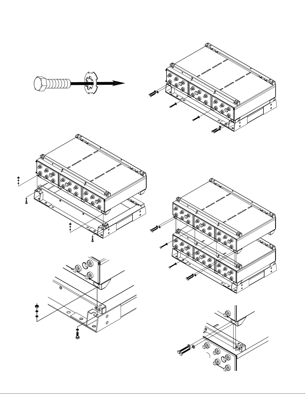
5. When lifting cells and modules, the proper equipment is needed
such as a forklift or a portable crane. Always check the lifting
capacities of the equipment being used and never lift more than
one module and or cell at a time.
Storage / Refresh
Cells should be installed, and float charged upon delivery. If cells
are to be stored, the below requirements shall be followed
1. Cells shall be stored indoors in a clean, level, dry, cool location.
2. Store, charge, and ship in horizontal position only.
3. Battery pallets shall not be double stacked, or equipment stored
on top.
4. Recommended storage temperature is 50°F (10°C) to 77°F
(25°C). Acceptable storage temperature is 0°F (-18°C) to 90°F
(32°C).
5. The cells shall be given a refresh charge at regular intervals as
detailed below:
0°F(-18°C) to 77°F (25°C)
Cells shall be charged by the “battery charge date” marked on
pallet.
Successive recharges shall be performed every 6 months.
a.3

Storage / Refresh Continued
78°F (26°C) to 90°F (32°C)
Cell voltage readings shall be taken monthly. Cells must be
given a refresh charge within 3 months from date of receipt or
if any cell voltage falls below 2.12 vpc, whichever occurs first.
Successive refresh charges shall be performed every 3 months.
6. Whenever a refresh charge is required, it’s important that all
batteries to be installed in the same series string receive a
charge at the same time to ensure continuity once placed in
their intended application.
7. Each cell shall be charged for 24 hours at a constant voltage equal
to 2.40 volts per cell. To ensure the cells are fully charged within
24hrs, the charger used for this refresh charge must have the
capacity to provide at least the minimum
charge current specification and not exceed the maximum charge
current for the given cell type (model), as called out in Appendix F
for Unigy II & Appendix G for Deka Fahrenheit HT 2V.
8. All requested information on “Refresh Record Form” in Appendix B
should be completed for each refresh charge.
9. Cells shall not be stored beyond 12 months. Storing beyond
12 months will affect warranty.
10. If the storage / refresh requirements cannot be met, contact East
Penn Reserve Power’s Product Support group for
alternate instructions.
INSTALLATION
General
Caution should be taken when installing cells to ensure no damage
occurs. Cells shall not be dropped, slid, or placed on rough or
uneven surfaces such as tray lips or grated flooring. Mishandling of
cells could result in equipment damage or human injury. East Penn
will not be liable for damage or injury as a result of mishandling or
misuse of the product.
NOTE: If battery monitoring system is installed prior to battery being
placed in service; monitoring system should remain off to prevent
discharging of battery.
Electrical Connections
When making electrical connections to the battery string, proper
techniques should be applied per electrical standards such as NEC
and/or Federal, State and Local codes, as well as User Manual of
specific application.
Grounding
When grounding the battery string, proper techniques should be
applied per electrical standards, such as NEC and/or local codes.
Two 0.201 diameter x 0.750 center holes are provided in back of
each module to accept a # 6 x 0.750 center compression grounding
lug. The holes must be tapped for a 1/4-20UNC thread and paint
must be removed for a proper grounding pad location.*
*Note: Battery string and/or stack to stack grounding, if
required, is the installer’s responsibility.
Electric Code for Maintenance Access
Refer to ANSI/NFPA-70 National Electric Code for access and work-
ing space requirements around the battery. A minimum of 36” aisle
space is recommended in front of the battery system for service
and inspection.
Hardware Torque Requirements
System Installation
System Shipment
Battery string will be received per drawing below.
Interlock Module Installation
Assemble battery string per the following details.
All parts should be verified against packaging list. Report any
missing parts.
1.
Remove floor-mounting base support from the top of the
modules. Base(s) are wire tied to module assembly.
2.
Position base(s). Consult included battery string layout diagram for
required base layout. If it can not be located, contact East Penn Mfg.
for a copy. Refer to your delivery number, located on the packing slip.
This will aid in obtaining the proper drawing.
3.
Bases are required to be level prior to installing modules.
Interlock Base
a.4
Bolt Size Torque
3/8-16 25 ft-lb 33.8 Nm
1/4-20 125 in-lb 14.1 Nm

4.
Anchor holes can be marked and drilled with bases in place.
Consult Appendix E for anchor hole pattern. All anchor holes
in base are required to be used to meet seismic requirements.
Consult local building codes for anchor
bolt requirements. Anchor bolts not included due to site
specific requirements.
5.
Remove hardware holding modules together and holding
modules to skid. Hardware removed from modules will be
reused to attach modules to bases and to each other. Hardware
holding modules to skid can be discarded.
6.
When leveling Interlock battery strings using a 1-piece base
support, it is critical to note that the back channel is 3/16"
shorter than the front channel. If a level is placed across the
front and rear channels, a 3/16" shim should be placed on
top of the rear channel in order to level properly. Refer to
“Interlock Leveling Diagram” below.
7.
Module / Base Shimming
a. Prior to installation, the floor on which the battery string is
to be installed should be level and capable of supporting the
weight of the battery string. A 1° taper on a floor can result
in a ½" variation at the top of one eight-high stack
of modules. This can be compounded by the tolerance of
each module.
b. Standard steel shim stock such as AISI/SAE 1010 can be
used. Stainless steel is not required since these batteries
are AGM and should not be exposed to a corrosive
environment. Shim dimensions will vary depending on the
location and levelness. Shims are not provided by East Penn
due to site specific requirements.
c. If floors are not level, shim material can be placed under
each of the base supports within a battery string until they
are level. All base supports within a battery string must be
level with each other – do not level individual bases as this
could cause variation in height from one stack to another.
a.5
d. It is recommend to place an interstack connector on the
system to ensure no stress will be placed on the cell posts.
Reference Safety Section of this manual and
battery schematic for all necessary precautions. If the
connector is aligned, it may be removed and the module
installation can continue.
e. Reference Appendix E for Base Support layout dimensions
f. Once all the modules are installed and aligned, joining
plates (pg a.8 Part 3) which are provided with the parts kit
should be installed at the top of every stack. This provides
an additional tool to ensure levelness.
g. Assuming these guidelines are followed, the electrical
connections can be installed easily without any issues
of misalignment or undue stress on the cell posts.
CAUTION: Never lift more than one module at a time with
the supplied lifting slings.
8. Install modules onto bases using supplied lifting straps. Two
straps required to lift each module. Consult below
diagram for proper sling attachment.
9. Installed battery string should be compared to battery string layout
drawing for correctness. As each module is installed
all hardware should be checked for proper torque before
proceeding to next module.
a.
Module slides into cut outs in back of base. Lower first
module onto base with module slightly forward. Slide module
towards back of base until locked into slots.
INCORRECT
CORRECT
Interlock Leveling Diagram

b. Module connecting hardware is furnished with a dragon tooth
washer in place of a lock washer and flat washer.
The dragon tooth washer is used to enhance the electrical
conductivity of the grounding system within a stack of
modules. To ensure the dragon tooth washer is installed
correctly; the curve of the washer must face away from the
bolt head. Stack to stack grounding electrical
conductivity is the responsibility of the installer.
a.6
c. For seismic applications two – 3/8-16 x 1.00" bolts are
required to be installed as per below.
d. Connect the module to the base with a maximum of six –
3/8-16 x 1.25"bolts & dragon tooth washers in the front
only. Consult “Hardware Torque Requirements”
(pg a.4) for proper torque values.
e. Connect the modules to each other with a maximum of six
3/8-16 x 1.25"bolts & dragon tooth washers installed in the
front of the modules. Process to be repeated until all modules
are installed. Consult “Hardware Torque Requirements” (pg a.4)
for proper torque values.

10.
Module layout should be compared to battery string layout
diagram and all hardware should be checked for proper torque
before proceeding. Consult “Hardware Torque Requirements”
(pg a.4) for proper torque values.
2.
Safety shield brackets are to be installed at the top of the
module in the same manner as detailed previously. Tighten, do
not torque hardware.
a.7
Safety Shield Bracket Assembly
1.
Safety shield brackets are to be installed at the outside
corners of every 2 modules starting from the bottom and working
towards the top. This is to be repeated for each stack in the
battery system. For stacks containing odd number of modules
an additional set of safety shield brackets will be required to be
installed at the top of the module. Use
3/8-16 x 2.50"hardware to install brackets. Bracket should
be flush with side of module to ensure correct safety shield
alignment. Tighten, do not torque hardware.

3.
For multiple stack systems, joining plates are to be installed at
the front of the modules at the top of the stacks. One joining
plate is to be used at the junction of two modules. Use the 3/8-
16 x 2.50"hardware used to connect the safety shield bracket
together. Stack to stack grounding electrical conductivity is
the responsibility of the installer.
a.8
Electrical Connection
Connector Assembly
1.
The contact surfaces of each individual post on every cell
have been cleaned and coated with a thin film of No-Ox-ID “A”
grease at the factory. Assure the contact surfaces are free of
dust or dirt prior to assembly.
2.
The battery string is supplied with a connector package
appropriate to the required load the battery string is connected
to. Review the below chart “Connector Packages” to ensure the
correct connector package has been supplied.
CONNECTOR PACKAGES
Type Plate AMPS WPC
1CU
5 - 15 ≤250 ≤480
17 - 27 ≤450 ≤720
29 - 33 ≤550 ≤880
2CU 5 - 33 ≤900 ≤1440
4CU 5 - 33 ≤2000 ≤3200
6CU 5 - 33 ≤3000 ≤4800
BOLT PACKAGE
1CU 1/4-20 x 1.25"
2CU 1/4-20 x 1.50"
4CU 1/4-20 x 1.75"
6CU 1/4-20 x 2.00"

3.
Installation and direction of the cell post hardware is
important. Consult below diagram for clarification.
a.9
29 to 33 Plate
5 to 15 Plate
17 to 27 Plate

2CU Package Detail
6CU Package Detail
4. Unigy II & Fahrenheit HT 2V
battery strings are typically supplied with connector package 1CU requiring one connector per post.
a.10
5.
High rate applications will require multiple connectors to be used per cell post. A 2CU connector package will require 2 connectors per connection
(1 per side), see example below. A 4CU package will require 4 connectors per connection (2 per side) and a 6CU package will require 6 connectors
per connection (3 per side). Tighten & torque all bolts after all connectors are installed. Consult “Hardware Torque Requirements” (pg a.4) for
proper torque values.
4CU Package Detail
Este manual sirve para los siguientes modelos
6
Tabla de contenidos
Manuales populares de Almacenamiento de otras marcas

Spectra Logic
Spectra Logic T-Series Spectra T50e Manual de usuario

Panasonic
Panasonic LKM-F931-1 Manual de usuario

Tabernus
Tabernus Enterprise Erase E2400 Manual de usuario

Rocstor
Rocstor COMMANDER 3F series Manual de usuario

HP
HP P9000 Manual de usuario

Western Digital
Western Digital Ultrastar Data60 Manual de usuario


