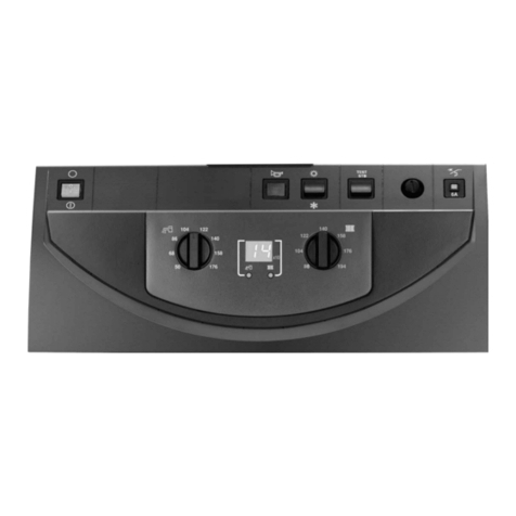
DeDietrich S3 Manual de usuario

M000483
l
0
30
10A
TEST
STB
S3 standard control panel
Installation
instructions
Technical
instructions
English
23/01/06
Package MD4

2Control panel S3 23/01/06 - 300008905-001-A
Contents
Symbols used. . . . . . . . . . . . . . . . . . . . . . . . . . . . . . . . . . . . . . . . . . . . . . . . . . . . . . . . . . . . . . . . . . . . . . . . . . . . . . . .3
Important recommendations . . . . . . . . . . . . . . . . . . . . . . . . . . . . . . . . . . . . . . . . . . . . . . . . . . . . . . . . . . . . . . . . . . .3
Description . . . . . . . . . . . . . . . . . . . . . . . . . . . . . . . . . . . . . . . . . . . . . . . . . . . . . . . . . . . . . . . . . . . . . . . . . . . . . . . . . .4
Presentation . . . . . . . . . . . . . . . . . . . . . . . . . . . . . . . . . . . . . . . . . . . . . . . . . . . . . . . . . . . . . . . . . . . . . . . . . . . . . . . . .5
Commissionning . . . . . . . . . . . . . . . . . . . . . . . . . . . . . . . . . . . . . . . . . . . . . . . . . . . . . . . . . . . . . . . . . . . . . . . . . . . . .6
Mounting - Connections . . . . . . . . . . . . . . . . . . . . . . . . . . . . . . . . . . . . . . . . . . . . . . . . . . . . . . . . . . . . . . . . . . . . . . .7
1 Control panel assembly . . . . . . . . . . . . . . . . . . . . . . . . . . . . . . . . . . . . . . . . . . . . . . . . . . . . . . . . . . . . . . . . . . . . . . . . . . . . . . . . . . . . .7
2 Electrical connections. . . . . . . . . . . . . . . . . . . . . . . . . . . . . . . . . . . . . . . . . . . . . . . . . . . . . . . . . . . . . . . . . . . . . . . . . . . . . . . . . . . . . . .7
3 Access to the connection terminal . . . . . . . . . . . . . . . . . . . . . . . . . . . . . . . . . . . . . . . . . . . . . . . . . . . . . . . . . . . . . . . . . . . . . . . . . . . . .7
4 Electricity supply - Flow controller . . . . . . . . . . . . . . . . . . . . . . . . . . . . . . . . . . . . . . . . . .. . . . . . . . . . . . . . . . . . . . . . . . . . . . . . . . . . .8
5 Connecting the burner . . . . . . . . . . . . . . . . . . . . . . . . . . . . . . . . . . . . . . . . . . . . . . . . . . . . . . . . . . . . . . . . . . . . . . . . . . . . . . . . . . . . . .9
6 Connecting the safety thermostat alarm report . . . . . . . . . . . . . . . . . . . . . . . . . . . . . . . . . . . . . . . . . . . . . . . . . . . . . . . . . . . . . . . . . .11
7 Connecting the flue gas thermometer (Package BP28). . . . . . . . . . . . . . . . . . . . . . . . . . . . . . . . . . . . . . . . . . . . . . . . . . . . . . . . . . . .12
Skeleton Diagrams. . . . . . . . . . . . . . . . . . . . . . . . . . . . . . . . . . . . . . . . . . . . . . . . . . . . . . . . . . . . . . . . . . . . . . . . . . .13
Spare parts . . . . . . . . . . . . . . . . . . . . . . . . . . . . . . . . . . . . . . . . . . . . . . . . . . . . . . . . . . . . . . . . . . . . . . . . . . . . . . . . .14

3
23/01/06 - 300008905-001-A Control panel S3
Symbols used
Caution danger
Risk of injury and damage to equipment. Attention must be
paid to the warnings on safety of persons and equipment
Specific information
Information must be kept in mind to maintain comfort
ZReference
Refer to another manual or other pages in this instruction
manual
DHW: Domestic hot water
Switch off the power supply before doing the work!.
This appliance must be connected to the earth.
Important recommendations
For a proper operating of the boiler, follow carefully the
instructions.
Any intervention on the appliance and heating equipment
must be carried out by a qualified technician.
The manufacturer is not liable for any improper use of the
appliance or failure to maintain or install the unit correctly
(the user shall take care to ensure that the system is
installed by a qualified fitter).
Keep to the polarity shown on the terminals : phase (L),
neutral (N) and earth 4.

4Control panel S3 23/01/06 - 300008905-001-A
Description
1Introduction
Standard electromechanical control panel for heating installations
without a control unit or for those which include a boiler room control
cabinet.
Thecontrolpanelis used tocontrolboilerswith 1 or 2-stage burners.
The control panel S3 equips the boilers GT 330.
optional:
Flue gas thermometer (Package BP28)
2 Presentation
Control panel S3 includes:
- 2 Boiler thermostats
- 1 Safety thermostat
The boiler thermostat regulates the boiler operating temperature.
The safety thermostat with manual reset ensures that the boiler
operates safely.
In the event that there is an abnormal rise in the
temperature in the boiler 110° C. Advise your installation
engineer.
3 Operating principle
The boiler may be regulated:
- either by the boiler thermostats
If the boiler is fitted with a 2-stage burner, each thermostat is
assigned to the operation of one stage. The 2nd stage
thermostat must be set to a value at least 5°C lower than the 1st
stage thermostat.
- or by a control unit located in a cabinet
Operating security is provided by the safety thermostat with
manual reset.
4 Technical characteristics
Compliance / Stamp 1
ThisproductcompliestotherequirementstotheEuropeanDirectives
and following standards:
- 73/23/EEC Low Voltage Directive
Reference Standard : EN 60.335.1
- 89/336/EEC Electromagnetic Compatibility Directive
Generic standards : EN1000-6-3 ; EN 61000-6-1

5
23/01/06 - 300008905-001-A Control panel S3
Presentation
1. General ON (1) / OFF (0) switch
2. Switch Test-STB
Temporary action to test the safety thermostat
3. Boiler thermostats (30 to 85 °C)
A factory-setstop limits themaximum temperatureto 75 °C. The
stop may be moved if necessary (See Moving the thermostat
stop).
4. Boiler thermometer
5. Location for flue gas thermometer (optional)
6. Timed circuit breaker (10 A) with delayed action and manual
reset
7. Safety thermostat with manual reset
(set to 110 °C)
76 1234
l
0
30
10A
M000484
5
TEST
STB

6Control panel S3 23/01/06 - 300008905-001-A
Commissionning
The first start-up is to be performed by your installation
engineer.
Beforestartingtheboiler,checkiftheinstallationis filled with water.
Start the boiler in the following order :
•Boiler temperature regulation by means of the thermostats
`Set the boiler thermostats 3to the desired position. The 2nd
stagethermostatmust be set to avalue at least 5°C lower than
the 1st stage thermostat.
If there is no control unit, we advise you never to set the
boiler thermostat below mark 4 (approx. 40°C) in order to
avoid the risk of combustion products condensing on the
walls of the boiler.
`Ifnecessary, change the position of the maximim temperature.
• Moving the thermostat stop
A factory-set stop limits the maximum temperature to 75 °C.
To move the stop, proceed as follows:
`Pull the thermostat button out carefully (use pliers and a cloth).
`Remove the stop with the pliers.
`Put the stop in the hole of the desired higher temperature
(maximum 85°C).
• Control unit in boiler room electrical cabinet
See the instructions supplied with the control unit and any
remote control unit used.
•Check that safety thermostat 7 is properly set. To do so,
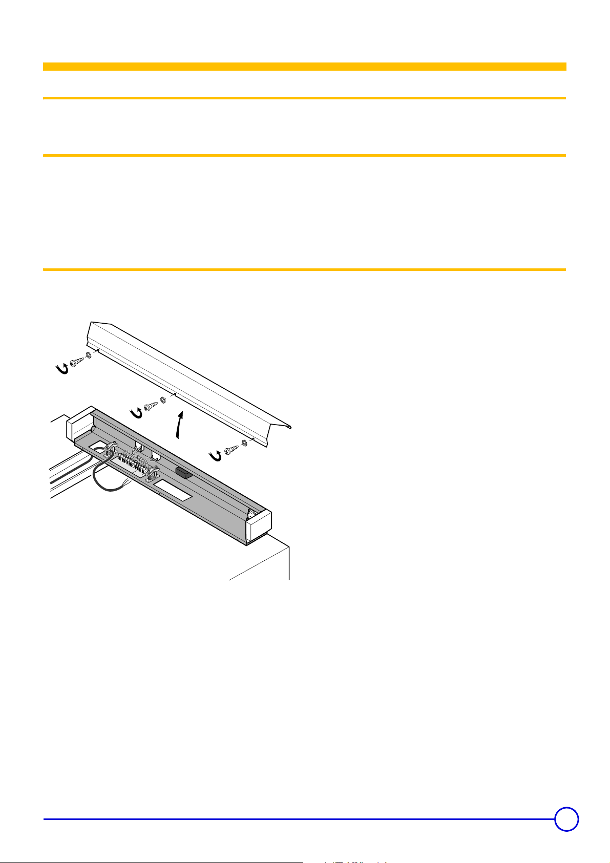
Unscrew the safety thermostat cover and press the reset button
using a screwdriver.
•Set the On/Off switch to 1.
9
8
7
6
5
M000154

7
23/01/06 - 300008905-001-A Control panel S3
Mounting - Connections
1 Control panel assembly
ZRefer to the technical and assembly instructions delivered with
the boiler.
2 Electrical connections
Only qualified professionnals may carry out electrical
connections, always with the power off.
As the electrical wiring has been carefuly checked in the
factory, the internal connections on the control panel must
not be changed in any way.
Electrical connections must match the electrical diagrams delivered
with the equipment and comply with the instructions in the manual.
Theequipmentmusthaveapowersupplyequipped witha omnipolar
switch with an opening distance above 3 mm.
The earth must comply with the NFC 15.100 (France) or the RGPT
(Belgium) standards.
3 Access to the connection terminal
All connections are made with the terminal boxes designed for
that purpose on the back of the boiler's command board.
Bringtheconnectingcablestothecontrolpanelthroughtheopenings
located on the rear panel of the boiler and 1 or 2 cable channels,
depending upon the type of boiler.
Attach the cables to the cable clamps provided for this purpose.
Keep to the polarity shown on the terminals : phase (L), neutral (N)
and earth 4.
1
21
1
10
9 8 7 6 5
4
V
AS
3
T8
T
7
T
6T
2
T
1
L
1 N
23
0
V
5
0
H
z
L
N
A
L
I
8555N056

8Control panel S3 23/01/06 - 300008905-001-A
4 Electricity supply - Flow controller
Make the electrical connection to the terminals 1, 2, 3.
Connection to the mains is done using a 3-wire cable with a cross
section of 0.75 mm² on the terminal block (terminals 1, 2, 3).
Forotherelectricalconnections,usethe3wirecablewithadiameter
of 0.75 mm².
The flow controller contact is connected to the safety circuit in series
(between terminal 5on the terminal block and terminal L1 on the
burner, for example).
34 21
567
89101112
LN
ALI
5 467
89101112
230 V / 50 HzNL1T1T2
T6T7T8S3VA
8219N087
2
3 x 0,75 mm

9
23/01/06 - 300008905-001-A Control panel S3
5 Connecting the burner
• Burner cable
7-pin plug for 1-stage burners or stage 1 of 2-stage burners
4-pin plug for stage 2 of the burner
Connector block with connection pins to the control panel
terminal block
The control panel is supplied with the burner power cable.
One end of this cable is fitted with two European 7 and 4 pin sockets
and the other with a terminal with male connecting pins.
• Control panel
Connect the terminal block to terminals 4 to 12 on the fixed terminal
block on the control panel using the male pins.
•Burnerside
Burner fitted with pin connectors
Refer to the burner cable diagram.
Burner without plug-in connectors
In this case, the connectors supplied with the burner cable must be
rewired.
Thediagramshowsthewirenumbersandtheterminalsof theburner
connectors.
8555N249
2 31
12 11 1 0
9
8 7 6 5 4
V
A S3T
8
T7
T6 T
2
T1
L
1 N
2
3
0V
5
0H
z
L
N
A
L
I
8555N058
B4 S3 T2 T1 N
V/J
L1 B5 T6 T7 T8
8456 7 1 32
8555N203

10 Control panel S3 23/01/06 - 300008905-001-A
The table below specifies the way in which the cables are to be
connected on the burner control box.
If the electrical characteristics of the burner exceed the following
values
- inrush current > 16 A or
- P > 450 W or
-I>2Acosϕ = 0.7
The burner controls must be relayed, e.g. with the relaying kit
(package BP 51, optional)
.
7-pin plugs for connecting to the control panel and burner
connectors.
Connector
terminal -No Wire No From Connection to the burner control box
L1 7 Continuous phase from the safety thermostat Burner main supply
4V/J Earth connection Earth connection
N6Neutral taken after On/Off Neutral terminal
T1/T2 5/4 Dry contact of the stage 1 boiler thermostat Insert in the control circuit of boiler stage 1
S3 8 Burner alarm indicator Alarm output (phase)
T6 1 Stage 2 boiler thermostat input Insert in the control circuit of burner stage 2
T7 3 Stage 2 “boiler off” thermostat output Connect only if the burner is of the modulating type
T8 2 Stage 2 “boiler on” thermostat output Insert in the control circuit of burner stage 2
M000150
1
Tabla de contenidos
Otros manuales de Panel de control de DeDietrich
DeDietrich
DeDietrich IniControl Guía de solución de problemas

DeDietrich
DeDietrich B control panel Manual de usuario

DeDietrich
DeDietrich EASYMATIC Manual de usuario

DeDietrich
DeDietrich Diematic iSystem Guía de solución de problemas

DeDietrich
DeDietrich MIT/E iSystem Manual de usuario
DeDietrich
DeDietrich IniControl 2 Instrucciones de funcionamiento

DeDietrich
DeDietrich DIEMATIC 3 Manual de usuario

DeDietrich
DeDietrich S2NA Manual de usuario