
DeAgostini Model Space RB7 Manual
Red Bull Racing RB7: Step by Step
™
1
Stages 1-4
RADIO CONTROLLED • BUILD IT YOURSELF • NITRO ENGINE
RB7
Pack 1
™
Red Bull Racing RB7: Step by Step
™
2
RB7
Editorial and design by Continuo Creative, 39-41 North Road, London N7 9DP
All rights reserved © 2013 De Agostini UK Ltd, Battersea Studios 2, 82 Silverthorne Road, London SW8 3HE
NOT SUITABLE FOR CHILDREN UNDER THE AGE OF 14. THIS PRODUCT IS NOT A TOY AND IS NOT DESIGNED OR
INTENDED FOR USE IN PLAY. RED BULL RACING RB7 complies with CE regulations. Items may vary from those shown.
Photo credits All photographs copyright
© DeAgostini
Visit our website www.model-space.com
Contents
Intro
An overview of your RB7 Racer
Stage 1
Assembling the front wing
Stage 2
Assembling the rear wings
Stage 3
Assembling the front wing
Stage 4
The rst shock absorber
Page 1
Page 5
Page 7
Page 11
Page 15
Red Bull Racing RB7: Step by Step
™
1
MODERN TECHNOLOGY AND A RANGE OF TUNING OPTIONS MAKE
THE RED BULL RACING RB7 RACING CAR A FASCINATING MODEL FOR
BEGINNERS AND EXPERIENCED MODELLERS ALIKE.
YOUR RED BULL
RACING RB7 AT
A GLANCE
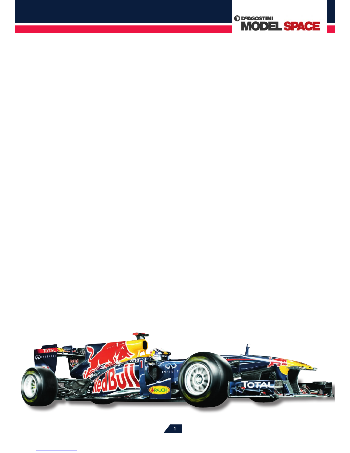
Fitting detailed display bodywork makes the Red Bull Racing RB7 model
a very realistic representation of Sebastian Vettel’s car. An additional
racing body is supplied for use on the track, so there is no need to risk
damaging the display body when the car is in action.
Based on Kyosho’s proven technology, your 1:7-scale
model Red Bull Racing RB7 delivers exciting motor
racing action. With its rear-mounted engine powering
the rear wheels – as on the full-sized original Red Bull
Racing RB7 – its nimble handling and rapid acceleration
promise an entertaining, authentic driving experience.
EASY ASSEMBLY
Assembling the model is simple and straightforward,
even for inexperienced modellers. Simple step-by-step
instructions take you through the assembly process
in easy stages. Each component is illustrated for easy
identication, and its installation is clearly explained.
And with each pack, alongside the assembly guides,
introductory articles will provide a wealth of in-depth
background information about RC modelling.
THE ENGINE AND TRANSMISSION
This little car is a thoroughbred circuit racer, and with
its 3.5cc nitro motor, it has enough power to challenge
any of its competitors on the track. The Red Bull Racing
RB7 is driven by the powerful Kyosho GX21 engine,
which delivers 1.8 horsepower at the crank. Being a
short-stroke design (with 16.6 x 16mm bore and stroke),
it is free-revving, with an even spread of torque. The
engine delivers great acceleration from standstill, as
Red Bull Racing RB7: Step by Step
™
2
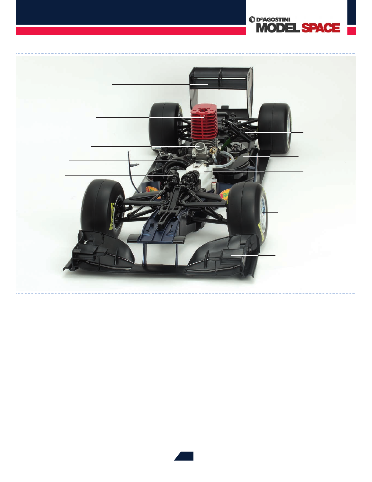
Plastic fuel tank
RC receiver and
batteries
Rear wing
GX21 motor
Carburettor
Transmission
Pushrod-operated
damper
Multi-element front
wing
Recoil starter
Accurately modelled
wheels and tyres
well as at higher speeds – enough to see o the stiest
competition. The car’s simple single-speed transmission
saves having to make complex adjustments to ensure
that the GX21 achieves its optimum performance on the
track, and is driven by the engine through an automatic,
centrifugal clutch.
To ensure a long, trouble-free life, the transmission
is made of tough high-performance plastic, while
the engine’s twin ball bearings reduce wear, and its
technically sophisticated, aerodynamic aluminium
cylinder head provides excellent cooling. (The GX21
engine is designed to operate only with model fuels with
a nitro content of 15-25%, and is not suitable for use with
other fuels).
THE CHASSIS
The centrepiece of the Red Bull Racing RB7 model – its
race-proven chassis – provides numerous adjustments
so that the performance of the car can be precisely
matched to a specic track or the personal preferences of
the driver. For example, the ride height can be adapted
to suit the individual characteristics of dierent race
circuits.
The car has four hydraulic dampers – and, in a similar
way to a full-size Formula 1 car, the front ones are
installed horizontally, operating via pushrods that link
them to the suspension wishbones. Together with the
sti, well-balanced chassis and the grippy tyres, this
gives your Red Bull Racing RB7 optimum stability when

Red Bull Racing RB7: Step by Step
™
3
With its large ns (anodised red to prevent corrosion), the
aerodynamically designed cylinder head ensures optimum cooling of
the GX21 engine under all driving conditions. The handle of the recoil
starter can be seen on the right, in front of the cylinder head.
cornering. Even under the fastest acceleration, the large
90 x 52mm rear tyres deliver the traction of the GX21
engine to the track, while smaller 90 x 45mm front tyres
handle the steering. Along with the rear-wheel drive
system, this set-up allows hot burnouts and fast drifts
that would not be possible with four-wheel drive cars,
providing an‘authentic’ Formula 1 feel, and long-lasting
driving pleasure on the circuit. The all-important ability
to decelerate is provided by a powerful central disc
brake built into the drive train, which slows down the
two rear wheels of the car.
THE BODYWORK
The 1:7-scale Red Bull Racing RB7 racer is an impressive
689 x 250 x 150mm with its bodywork tted. During
the course of the series, you’ll be building a ‘showcase
display’ body that is an authentic miniature of Sebastian
Vettel’s Red Bull Racing RB7,down to the smallest detail.
This includes the prominent Red Bull and sponsors’
logos, which are exact replicas of the originals, supplied
in the form of self-adhesive decals. You have received
the rst components for the display body with this pack,
and on page 5, you can start to assemble some of the
elements that go together to make up the front wing –
one of the most important aerodynamic elements of the
full-size car.
When the display body is complete, it will make
the model a star in any showcase – but you naturally
won’t want to submit it to the rigours of the racetrack,
and possible damage. So, in addition to the display
bodywork, towards the end of the series you will be
provided with a second, robust racing body to t your
model. This is also a detailed replica of the body of
Vettel’s car, but has been specially designed for use
on the racetrack, so that it will survive minor racing
incidents without damage. In particular, while the wings
and other external aerodynamics of the racing body are
still very much the same as that of the full-size Red Bull
Racing RB7, they are made a little more robust for racing
purposes. The racing body can be swapped for the
display body and tted in just a few simple steps. Then,
even if the car is involved in a major collision, or swerves
o the track, the tough bodywork and strong chassis
should prevent the model from suering any serious
damage.
THE REMOTE CONTROL SYSTEM
Your model Red Bull Racing RB7 is designed to work
with a Kyosho Syncro digital remote control system. This
has a handset that sends out signal pulses to operate
the model’s steering, throttle and brake, via a radio that
operates in the 2.4GHz band, transmitting through an
integrated antenna. Unlike an analogue system, a digital
remote control requires no special tuning and after
switching on, the handset will link up with the model by
means of a coded ‘handshake’ signal that prevents any
interference with other RC systems.
The driving controls are mounted on a pistol grip,
which is more comfortable to use than a simple joystick.
The trigger on the grip controls the car’s acceleration

Red Bull Racing RB7: Step by Step
™
4
The model’s steering servo can be seen on the right of the picture,
mounted behind the front suspension dampers – which are installed
horizontally and operated by pushrods.
During the course of the collection, you will have the opportunity to
acquire a superb 2.4GHz radio control system, including a receiver. If you
already have a suitable remote control system, however, you will be able
to use it to operate your Red Bull Racing RB7.
and deceleration, while a‘steering wheel’ on the
side makes the model turn. Other features of the
handset include a servo reverse, and an LED display
that indicates the charge of the four batteries housed
in a compartment underneath. The sophisticated
technology of the Kyosho Syncro remote control device
means that it is even possible to use it to operate several
dierent vehicles. The digital system that enables this is
available as an accessory.
MODERN ELECTRONICS
The radio signals from the remote control handset are
picked up by an RC receiver unit located in the radio box
on the chassis of your Red Bull Racing RB7 racing car,
on the left of the engine. The receiver unit converts the
radio signals into electrical pulses and passes them on
to the car’s control servos, which operate the throttle,
brake and steering. The servos have a very compact
design, and are tough enough to withstand the forces of
acceleration or deceleration acting on them.
ON THE TRACK
After you have completed your racing car, it is ready
to be started for the rst time. Later in the series, this
section of the pack will tell you everything you need to
know about preparing your model Red Bull Racing RB7
for its rst run under power, and how to adjust the car
and its engine to achieve the best possible performance.
You will also nd detailed information on using many
other features of the model, such as how to tailor the
chassis specically for the particular track on which you
are racing.
Red Bull Racing RB7: Step by Step
™
5
Phillips screwdriver (size 0)
Tools & Materials
7
109
4
65 8
11
1
2
3
12
12
1
2
3
4
5
6
7
8
9
10
11
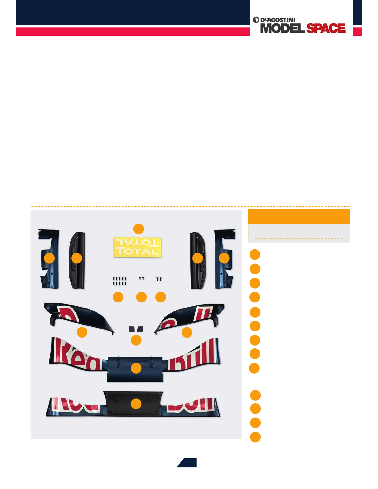
BEGIN THE ASSEMBLY OF YOUR REALISTICALLY DETAILED RB7 MODEL BY FITTING
TOGETHER THE LOWER AND CENTRAL PARTS OF THE FRONT WING, ALONG WITH
ITS LEFT AND RIGHT BASEPLATES.
ASSEMBLING THE
FRONT WING
Stage 1
Lower front wing
Centre front wing
Upper right front wing
Upper left front wing
Right front wing endplate
Left front wing endplate
Right front wing baseplate
Left front wing baseplate
10 countersunk screws,
1.4 x 4mm
2 cap screws 1.4 x 2.5mm
2 cap screws 1.4 x 4mm
Stickers
2 small upper fins
13
13
Red Bull Racing RB7: Step by Step
™
6
04
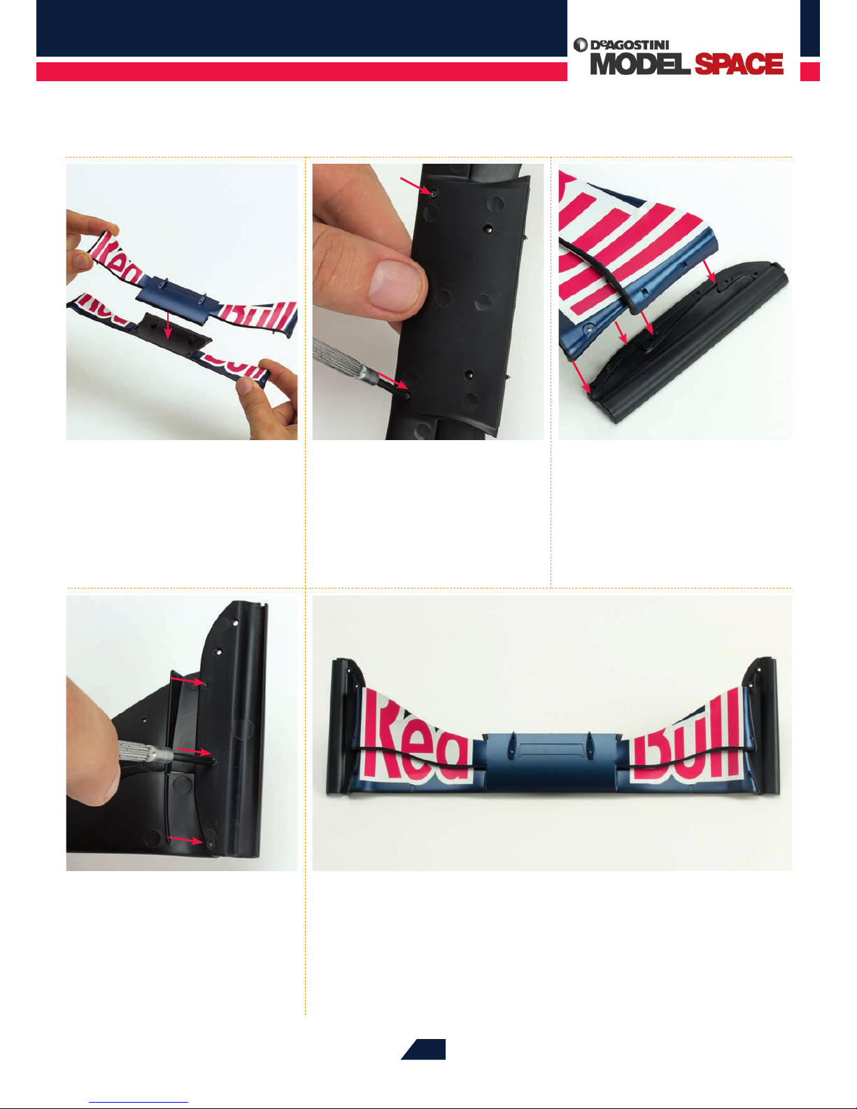
Fix the baseplate to the wing
by screwing three 1.4 x 4mm
countersunk screws into the three holes
(arrowed) on the underside. Repeat Steps 3
and 4 for the right side.
05
At the end of this rst stage of the assembly, the characteristic shape of the front
wing is already clearly visible. Store the wing in a safe place, along with any unused
parts, as these will be needed for future assemblies. It is recommended that you keep the
parts in a box with several compartments, so that even very small components are unlikely
to be lost.
01
Place the centre front wing on
the lower front wing, as shown.
The middle part of the centre front wing
should be ush with the front edge of
the lower wing.
02
Turn the assembly over. Take the
two 1.4 x 2.5mm screws and
x them into the two holes on the
underside of the lower front wing (as
arrowed), using a Phillips screwdriver.
03
Lay the left front wing baseplate
on your work surface, as shown.
Position the left side of the front wing
above it, so that its two ends are located
exactly above the two raised areas on the
baseplate (see arrows).
Red Bull Racing RB7: Step by Step
™
7
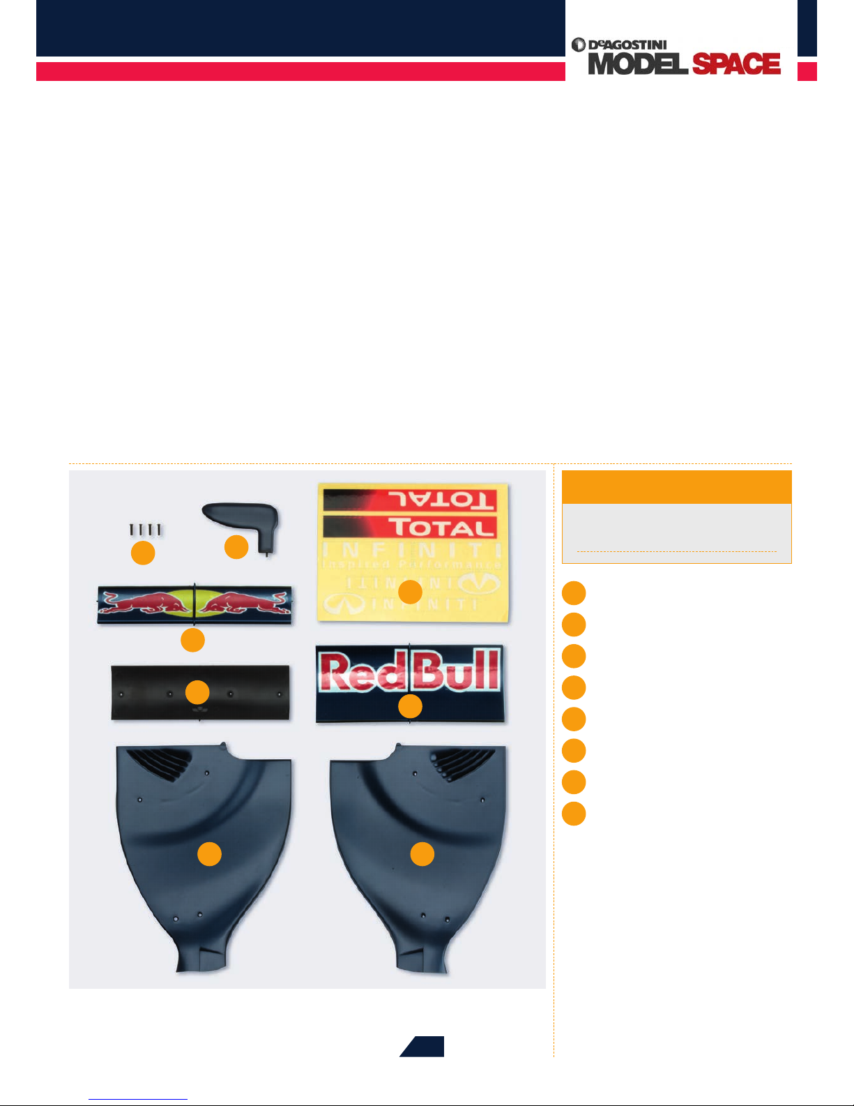
CONTINUE PUTTING TOGETHER THE COMPONENTS OF THE FRONT WING, FOLLOWED
BY ASSEMBLING THE COMPONENTS FOR THE REAR WING OF YOUR RB7 MODEL.
ASSEMBLING THE
REAR WINGS
Phillips screwdriver (size 0)
Superglue
Tools & Materials
1Rear upper wing
2Rear wing adjuster
3Rear middle wing top plate
4Rear wing endplate (left)
5Rear wing endplate (right)
6Rear middle wing baseplate
7Stickers
84 countersunk screws 1.4 x 6mm
7
3
4
6
8
1
2
5
Stage 2
Red Bull Racing RB7: Step by Step
™
8
04
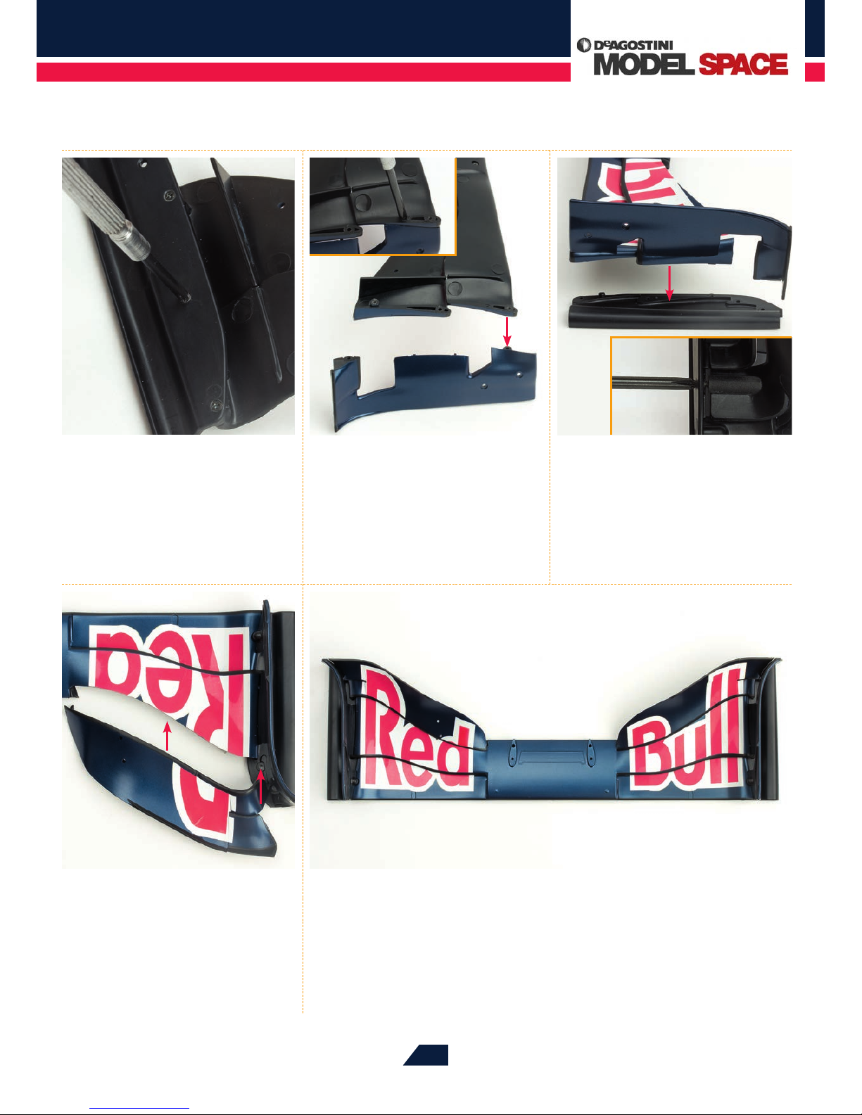
Place the upper right wing at the
rear of the wing assembly. Align the
holes at the arrow on the right and secure
using a 1.4 x 4mm screw. Repeat this step on
the left side.
05
This completes this phase of the front wing assembly. The front wing of your Red
Bull Racing RB7 should now look like the example shown above. Store the assembly
in a safe place until it is needed.
01
Lay the front wing on your work
surface with the underside
facing up. Using the Phillips screwdriver,
remove the six screws screwed through
the two baseplates into the wing, then
remove both baseplates.
02
Position the stored left endplate
as shown. Hold the front wing
above the endplate, so that the holes at
the front of both parts align (arrowed).
Connect both parts using a 1.4 x 4mm
screw. Repeat this step on the right side.
03
Position the right baseplate,
removed in Step 1, as shown.
Place the front wing onto the baseplate,
so that the proles on the underside
are located on the projections of the
baseplate (arrowed). Secure the parts
with three 1.4 x 4mm screws (inset), and
repeat this step on the left side.
Tabla de contenidos


