DCB PPP-SR Manual de usuario

8500056
PPP-SR
TABLE OF CONTENTS
SECTION 1 - DESCRIPTION.......................................................................2
SECTION 2 - SPECIFICATIONS.................................................................4
SECTION 3 - INSTALLATION.....................................................................5
SECTION 4 - CONTROLS AND INDICATORS .........................................6
SECTION 5 - NETWORK MANAGEMENT PORT.....................................9
SECTION 6 - INTERFACE SIGNALS AND CABLING...........................13
SECTION 7 - TROUBLESHOOTING .......................................................17
SECTION 8 - WARRANTY..........................................................................19
Data Comm for Business, Inc.
807 Pioneer Street
Champaign, IL 61820 March 1, 2000
217-352-3207 Firmware Version: 2.5

2
1. DESCRIPTION
The DCB PPP-SR is a simple router with one or four local
asynchronous ports, one synchronous WAN port, and synchronous to
asynchronous PPP translation. It connects remote PCs to the
Internet or an Intranet. The PPP-SR accepts IP encapsulated in
frame relay or synchronous PPP from a host router. It converts
these protocols to asynchronous PPP which is passed to the PCs
through its asynchronous com ports.
The PPP-SR also mimics a generic modem handshake to allow PCs
using Microsoft Windows95 (and similar Internet dialers) to use the
built in dial-up networking function, including its PPP protocol. Just
select the generic high speed modem, set up a fixed or dynamic
TCP/IP address, and go on-line.
The PPP-SR may contain a built-in 56/64Kbps DSU (PPP-SR01DSU
and PPP-SR04DSU models) for direct connection to leased telephone
lines. With a built-in DSU, it can be connected directly to DDS or
frame relay telephone company lines. Without the built-in DSU, it
must be connected to an external DSU, ISDN Terminal Adapter,
modem, radio, or FRAD.
Since it connects to the PC using a serial (COM:) port, the PPP-SR
provides a simple way to connect small remote offices or SOHO
locations to the host router without installing a complex LAN at the
remote office. It provides a dedicated remote connection without
the complexity that is normally associated with a LAN and remote
connections.
The PPP-SR is especially cost effective in areas with ISDN usage
billing and in areas where frame relay is economical. Multiple PPP-
SR sites can be connected to the same host router port through the
frame relay cloud. This allows a single host router port to support a
hundred or more remote sites.
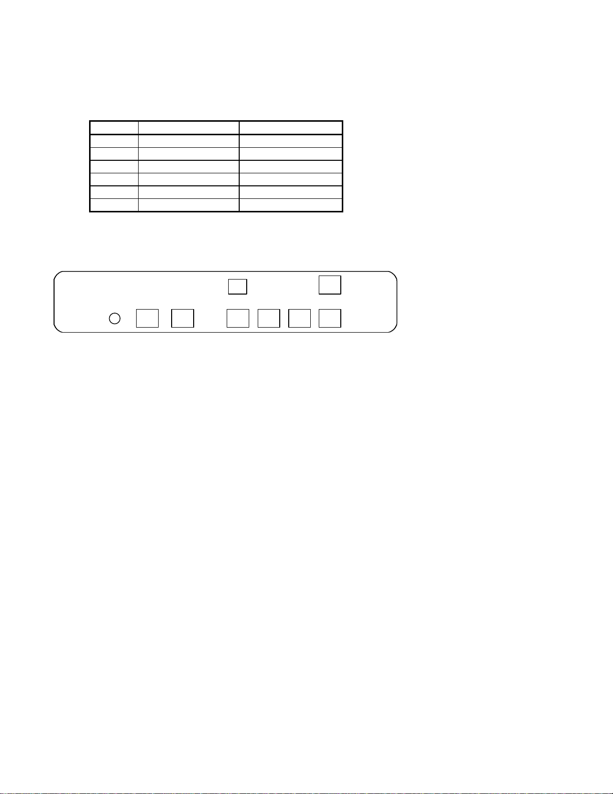
The PPP-SR is easy to install and operate. Controls on the unit
include the loopback push button and the Setup switch used to set
the asynchronous terminal interface to 115,200 bps if the user
chooses not to use the default rate of 57,600 bps. The minimum
number of controls and comprehensive indicators make installation
and troubleshooting easy. Diagnostic aids built into the PPP-SR
include LED indicators, ping, a management interface, and statistics.

3
Features
•56 or 64 Kbps line speed with optional built-in DSU
•Up to 128 Kbps line speed with external DSU
•RS-232 interface rates to 115.2 Kbps
•Converts synchronous PPP protocol to asynchronous PPP
•“AT” command spoofing for Microsoft Windows95 dialer and
similar dialers
•Use over DDS or DDS/frame relay
•Ideal for Internet or Intranets
•Cost effective versus router + NIC + HUB + DSU
•Reliable, high speed private line service alternative to dial-up
modems

4
2. SPECIFICATIONS
2.1 General
PC port interface: RS-232 implemented in 8-wire RJ-45 jack per
EIA/TIA 561
PC port rate: up to 115.2 Kbps asynchronous
Router Indicators: Power, Activity, Line Error, Modem Ready,
Port 1 Setup
DSU Indicators: Transmit Data, Receive Data, Request to Send,
Clear to Send, Data Carrier Detect, Test
DSU Telco Interface: 8-wire RJ-48S DDS (with built-in DSU)
Composite rate: 56 or 64 Kbps synchronous with built-in DSU
up to 128 Kbps with external DSU
2.2 Environmental
Operation: 0 to 65° C, 10 to 85% relative humidity
Storage: -40 to 85° C, 10 to 85% relative humidity
2.3 Physical / Electrical
10¼” W x 9¾” D x 2½” H
9 VDC external power supply
2.4 Management Port Commands
Help
Show Configuration
Show IP Address
Show Status (Frame Relay)
Configure Ports
Configure IP Address
Configure Options
Frame Relay Configure
Set Identifier
Activity Counter
Zero Counter
Type
Repeat Last Command
Disconnect NMP
Test Tools
Ping IP Address
Show RS-232
Reset SR

5
3. INSTALLATION
3.1 Unpacking
The following is included with each PPP-SR:
•PPP-SR and external power supply
•Cable for connection to an external DSU or phone line
•Cable for connection to a PC
•Manual
•Information regarding warranty, maintenance contracts and
repair
3.2 Location
Place the PPP-SR in a clear area where you can reach the front
panel for setup and the rear panel to connect the cables. The PPP-
SR has an external power supply that requires a 120 VAC outlet.
The power cord length is about 6 feet.
3.3 Setup
If an IP address is desired, use the Network Management Port CI
command to assign a WAN IP address to the PPP-SR. If the default
PC port rate of 57.6 Kbps isn’t wanted, use the CP command to set
the PC port rate to 9.6, 19.2, 38.4, 57.6, or 115.2 Kbps.
3.4 Connections
Using the cable provided, connect the line port to the DSU or phone
line. Connect PCs to the PC ports using the cable illustrated in
paragraph 6.3.1. One PC connection cable is supplied with the unit.
To connect more than one PC, optional cables must be ordered.

6
4. CONTROLS AND INDICATORS
4.1 Front Panel Controls (shown with built-in DSU)
4.1.1 Loopback Switch
Not Implemented
4.1.2 Setup Switch
Enables the unit to be configured using the PC connected to port 1. The
Port 1 Setup indicator will light. This makes port 1 operate as a
temporary set-up management port. In this state, port 1 should be
accessed using a terminal emulator program such as Hyperterm. Press
the switch again to return to normal operation.
4.1.3 Reset Switch
Performs a hardware reset. Configuration settings are retained
through the reset.
TXD RXD RTS CTS DCD TEST
SR DATA MULTIPLEXER
LINE MODEM PORT 1
POWER ACTIVITY ERROR READY SETUP LOOPBACK LOOPBACK SETUP RESET
DCB

7
4.2 Rear Panel Controls
4.2.1 Dip Switches (for built-in DSU only)
The DSU switches are located at the rear of the unit. Switch
functions are shown in the following table:
Switch Down Up
156K 64K (optional)
2Slave Clock Master Clock
3Must Be Down
4RTS Normal RTS Forced ON
5Normal Local Loop ON
6Not Used
NOTE
RTS mode (sw 4) is active in 56Kbps mode only. In 64Kbps mode,
RTS is forced on.
For normal operation with a telephone company line, set the DSU for
SLAVE clock timing (switch position 2 DOWN). For in-house line
driver applications (56K only), set the host DSU for MASTER timing
(switch position 2 UP). The remote unit should remain set for Slave
clock.
Network Network Switches DSU Telco
Power Management Port Composite 4 3 2 1

8
4.3 Indicators
Indicator Condition Meaning
Power ON Unit has power.
Activity ON Unit is in on-line mode.
Line Error Not Used
Modem Ready ON Network DCD is high.
Port 1 Setup ON
OFF
Network Management Port functions have
been mapped to Port 1 for unit
configuration. To return to normal
operation, press the front panel Port 1 Setup
switch.
Normal operation. Configuration must be
done from the Network Management Port.
Loopback Not used.
TxD Flashing Data is being sent over the link.
RxD Flashing Data is being received from the link.
RTS ON
OFF Forced on or high from the router
No RTS from the router.
CTS Follows RTS CTS signal to the DTE device
DCD ON
OFF Normal condition.
No carrier signal received from the far end.
TEST Flashing Telephone line in loopback.

9
5. NETWORK MANAGEMENT PORT
5.1 Introduction
The Network Management port (NMP) provides access to vital
statistics and troubleshooting tools. By connecting a terminal or
modem to the NMP a vast array of information is at your finger tips.
This information can also be accessed via a terminal device (or PC
using terminal emulation software) on port 1 when the port 1 setup
switch is depressed.
5.2 Connections and Setup
Connection to the NMP is made either through a port on the rear of
the router or by using Port 1 Setup.
5.2.1 Port 1 Setup
The easiest way to access the NMP functions is by using a terminal
or PC connected to port 1 of the router. A switch located on the front
panel performs this function. See paragraph 4.1.2 for information.
Once the switch is set, no further setup is required.
5.2.2 Dedicated Terminal
The NMP functions are also available through a port on the rear of
the unit labeled Network Management Port. To connect a dedicated
terminal to this port, use the cable described in paragraph 6.3.3. Set
the terminal for 9600 bps, 8 data bits, no parity and one stop bit.
5.2.3 Dedicated Modem
For remote access to NMP functions, a dial-up modem may be
connected to the Network Management Port. You must fix the DTE
interface speed of the modem at 9600 bps, 8 data bits, no parity and
one stop bit. Refer to your modem manual for appropriate setup
procedures. Use the appropriate cable from paragraph 6.3.3 for
connection.

10
5.3 Using the Network Management port
To activate the NMP, press the ENTER key. When you see AT
YOUR COMMAND >>, the NMP is active and ready for your
commands. Type H <Enter> to display the command set.
5.4 Commands
5.4.1 Help
Displays all available commands.
COMMAND PARAGRAPH
Show Configuration SC 5.4.2
Show IP Address SI 5.4.3
Frame Relay Status SS 5.4.4
Change Port Configuration CP 5.4.5
Change IP Address CI 5.4.6
Change Options CO 5.4.7
Change Frame Relay Conf. FR 5.4.8
Set ID ID 5.4.9
Activity Counters/Zero AC/Z 5.4.10
Test Tools TT 5.4.14
Type TY 5.4.11
Repeat Last Command *5.4.12
Disconnect NMP BYE 5.4.13
5.4.2 Show (Port) Configuration
Displays the current PC port rate. All PC ports are set at the same
rate.
5.4.3 Show (WAN/Port) IP Address
The Show IP Address (SI) command displays the assigned and actual
IP addresses for all ports and the PC port status. It also displays a
WAN IP address for the PPP-SR unit.
5.4.4 Frame Relay Status
The SS command displays the status of the frame relay connection to
the telephone company. This includes DLCI(s), counters, and other
management information
Tabla de contenidos


