DataON DNS-1640 Manual de usuario

DNS-1640
2U 24 Bays 6Gb/s SAS JBOD
Dual-path, Dual I/O
User Manual
Version QS0003
Copyright © 2014- DataON Storage. All rights reserved. www.dataonstorage.com

1
Copyright
This publication, including all photographs, illustrations and software, is protected under international copyright
laws, with all rights reserved. Neither this manual, nor any of the material contained herein, may be reproduced
without the express written consent of the manufacturer.
Copyright © 2011 DataON Storage Inc.
Trademarks
All product names used in this manual are the properties of their respective owners and are acknowledged.
Disclaimer
The information in this document is subject to change without notice. The manufacturer makes no representations
or warranties with respect to the contents hereof and specifically disclaim any implied warranties of merchantability
or fitness for any particular purpose. Furthermore, the manufacturer reserves the right to revise this publication
and to make changes from time to time in the content hereof without obligation of the manufacturer to notify any
person of such revision or changes.
Safety Measures
Computer components and electronic circuit boards can be damaged by discharges of static electricity. Working on
computers that are still connected to a power supply can be extremely dangerous. Follow these guidelines to avoid
damage to the DNS 1640 or injury to yourself.
•Always disconnect power when carrying out work inside the unit.
•If possible, wear a grounded wrist strap when carrying out work inside the unit. Alternatively,
discharge any static electricity by touching the bare metal chassis of the unit case, or the bare
metal body of any other grounded appliance.
•Hold electronic circuit boards by the edges only. Do not touch the components on the board un-
less it is necessary to do so. Do not flex or stress the circuit board.
•Leave all components inside the static-proof packaging until you are ready to install the compo-
nent.
Equipment Location
This equipment should only be accessed by SERVICE PERSONNEL or by USERS who have been instructed about
the reasons for the restrictions applied to the location. Access is through the use of a TOOL or lock and key, or
other means of security, and is controlled by the authority responsible for the location.
About this Guide
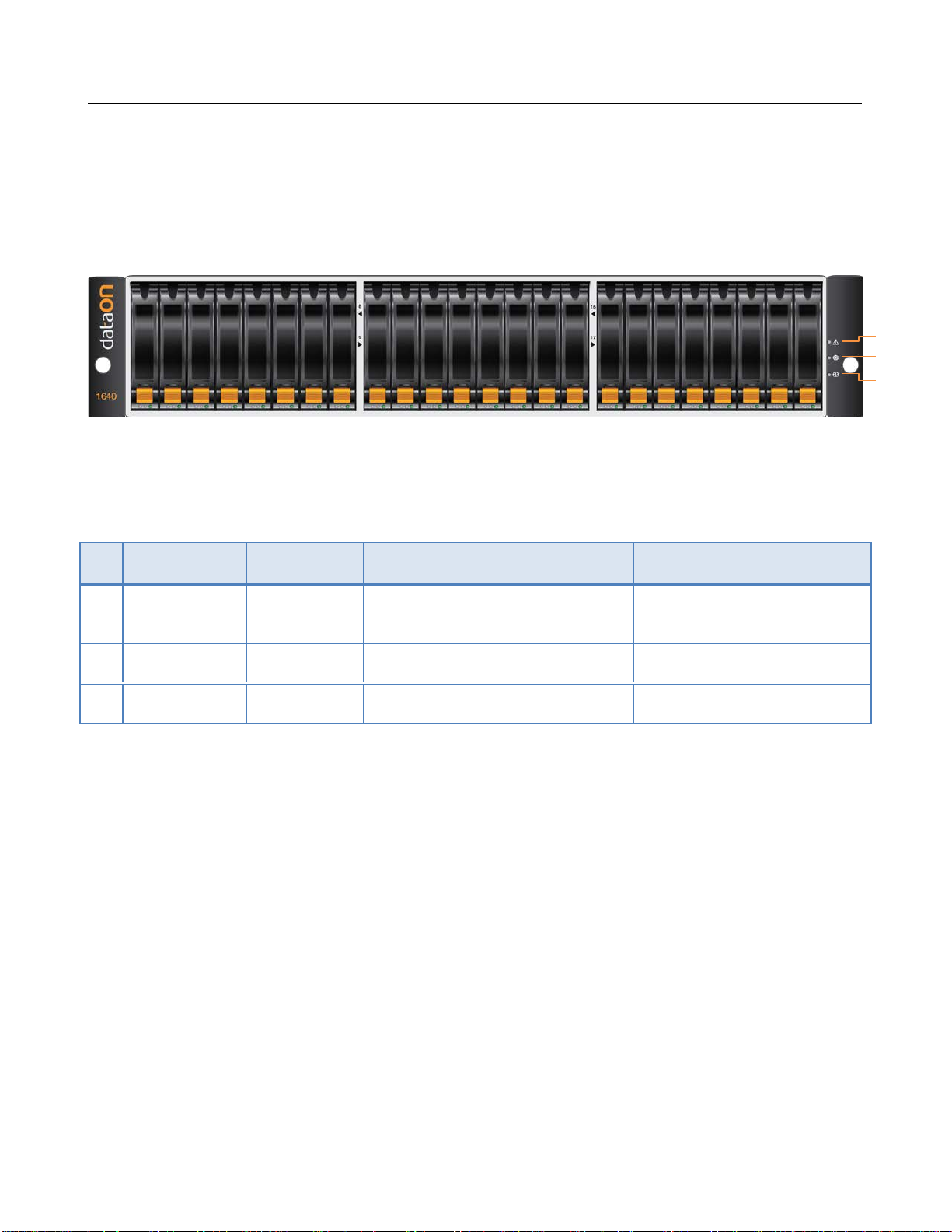
This guide describes how to setup and power on the DNS 1640 6Gb/s SAS JBOD system. This guide is intended for
trained personnel only.

DNS-1640 User Manual
2
Package content
The DNS-1640 box contains the following items:
•DNS-1640 Storage unit (1)
•Power cord (2)
•CD with user manual and drivers (1)
•Universal Rail Kit for DNS-1640 (1)
•HDD Screws(96)
System requirements
•Servers with supported HBA/Raid adapter, refer to DNS-1640 support matrix reference
for complete listing of supported adapters.
•SFF-8088 to SFF-8088 SAS cable(s).
Model
Model# DNS-1640SM DNS-1640DM DNS-1640SDNS-1640D
Hard Drive Type SATA/SSD SATA/SSD SAS/SSD SAS/SSD
SAS I/O Module 1 2 1 2
DNS-BJMB
2.5” Interposer
12 12 0 0
Technical Support
Contact your system supplier.

DNS-1640 User Manual
3
DNS-1640 Overview
LEDs on the Storage Enclosure
No Component Color Lights On Lights Off
1 Fault LED Amber A component within the storage en-
closure needs attention. Normal
2 Locate LED Flashing Blue Identifies a storage enclosure Normal
3 Power Green Power On Power Off
1
2
3

DNS-1640 User Manual
4
DNS-1640 (Single SIM) Rear View
DNS-1640 (Dual SIM) Rear View
Important: Note the direction of the power supply unit. Insert the power supply with the
right direction.
All SAS IN & OUT connectors are SFF-8088
Power Connector
Power Supply
Module 1
SIM
Board #1
SAS #2
Connector SAS #3
Connector
Power Supply
Module 2
SAS #1
Connector
Power Supply
Module 2
Power Connector
SIM
Board #1 SAS #2
Connector SAS #3
Connector
SAS #1
Connector SAS #2
Connector SAS #3
Connector
SAS #1
Connector
SIM
Board #2
Power Supply
Module 1

DNS-1640 User Manual
5
DNS-1640 SIM Board LED Description
LED ON SIM Board
No Component Color Lights On Lights Off
1 SAS #2 Fault Amber PHY connection cannot estab-
lished correctly No error had occurred
2 SAS #2 Active Green PHY connection established
correctly
No connection
3 SAS #1 Fault Amber PHY connection cannot estab-
lished correctly No error had occurred
4 SAS #1 Active Green PHY connection established
correctly
No connection
5 SAS #3 Fault Amber PHY connection cannot estab-
lished correctly No error had occurred
6 SAS #3 Active Green PHY connection established
correctly
No connection
7 Locate LED Flashing Blue Identifies SIM Normal
8 SIM Fault Amber Fault exist Normal
9 SIM Power Green Power On Power Off
1
3
2
4
6
5
Consoles for factory use only 7 8 9

DNS-1640 User Manual
6
DNS-1640 PSM Board LED Description
No Component Color Lights On Lights Off
1 DC Power Green DC Power On No DC Power
2 Locate LED Blue Identifies Power Module Normal
3 PSM Fault Amber Fault exist Normal
4 AC Power Green AC Power On No AC Power
1 2 3 4

DNS-1640 User Manual
7
Disk Drives Front LED and Tray
No Component Color Description
1 HDD Activity LED Solid Green SAS HDD is ready (SATA will be blank)
Blinking Green Spin up /Accessing
2 HDD status Blank HDD Ok
Blinking Blue Identify HDD
Solid Orange HDD fault
Blinking Or-
ange & Blue RAID Rebuilt
Blinking Blue HDD is ready to remove (HDD Activity LED will be blank)
HDD Tray
1
2
Optional DNS-BJMB
9252 6Gb/s SAS
Interposer for 2.5”
SATA SSD/HDD
Disk Tray Handle
Release button

DNS-1640 User Manual
8
Install/Replace HDD
Before You Begin
It is not recommend mixing different RPM SAS and SATA HDD in the same DNS-1640 system. If you have to,
please use the following figures below to plan where you will be placing the disk drives.
These figures represent fully-loaded DNS-1640 system with HDD.
However, the same guidelines apply even if you are filling some of the HDD slots with blank disk trays in the mix-
ing HDD setting.
Recommended Mixing SAS & SATA HDD Configurations
Unsupported SAS & SATA HDD Combinations
SAS HDD
SATA HDD
Do not include SAS and SATA
HDD in the same section!
SAS HDD
SATA HDD

DNS-1640 User Manual
9
Follow these steps below to Install/Replace HDD in the disk tray.
Step 1
a) Press the release button and open the disk tray handle.
b) Remove HDD carrier by pulling the disk tray handle out.
Este manual sirve para los siguientes modelos
4
Tabla de contenidos
Manuales populares de Almacenamiento de otras marcas

Spectra Logic
Spectra Logic T-Series Spectra T50e Manual de usuario

Panasonic
Panasonic LKM-F931-1 Manual de usuario

Tabernus
Tabernus Enterprise Erase E2400 Manual de usuario

Rocstor
Rocstor COMMANDER 3F series Manual de usuario

HP
HP P9000 Manual de usuario

Western Digital
Western Digital Ultrastar Data60 Manual de usuario


