Darfon B09ULF Manual de usuario
I
用户手册
Instruction Manual
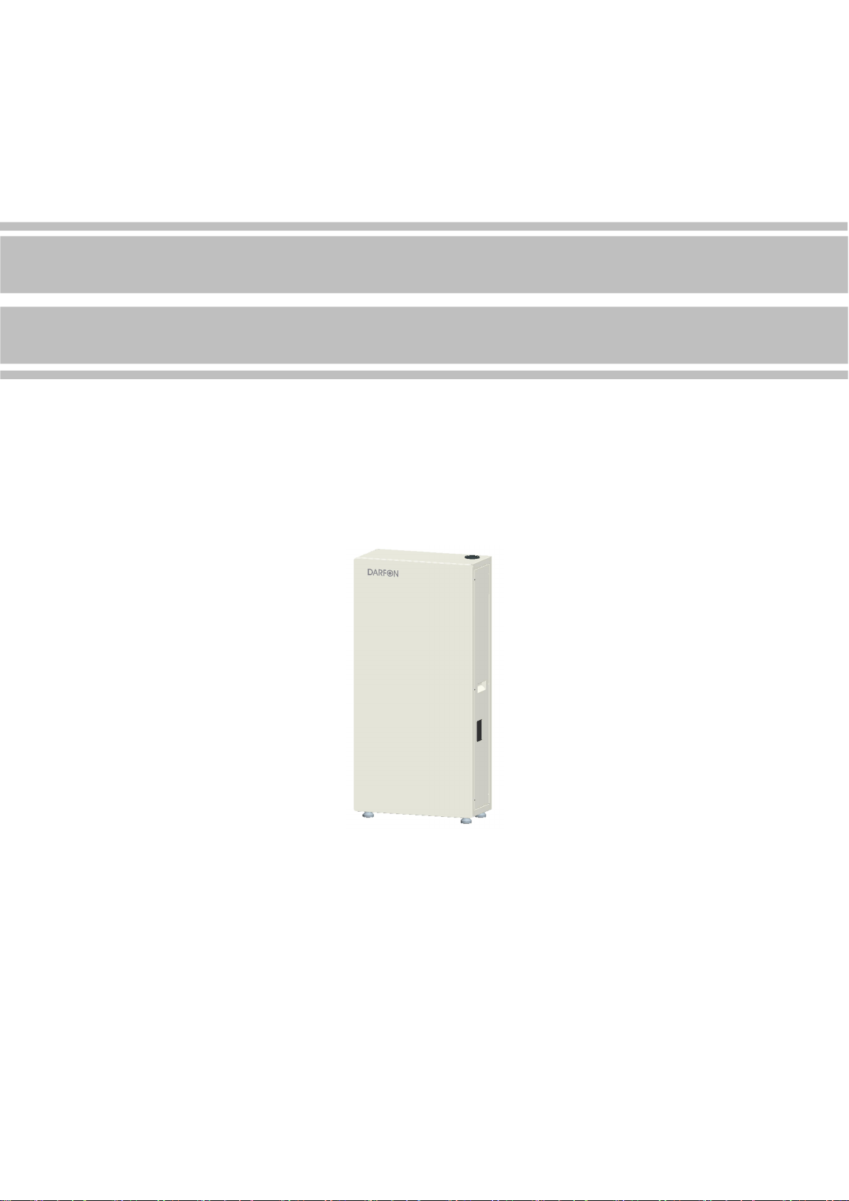
48V/9.6kWh Battery System
Model Number: B09ULF
Version:V1.3
Darfon Electronics Corp. Ltd.

1 / 47
Overview
Thank you for choosing the 48V/9.6KWh lithium battery system. The
system has innovative design and perfect quality management. It is safe,
stable, reliable and has a long service life. At the same time, the product is
easy to operate, easy to use, and has a series of perfect protection functions.
This manual focuses on the safe operation of the system. Please read this
manual carefully before proceeding. If you encounter any problems during the
operation of the device, please consult the corresponding instructions to solve
most problems in the installation and operation. Contact your dealer or supplier
if necessary.
Darfon Electronics Corp.
No.167,Shanying Rd.,Guishan Dist.,Taoyuan City 33341,Taiwan (R.O.C.)
TEL : +886-3-250-8800
Fax : +886-3-359-6677
Darfon America, CORP.
103a Pioneer Way
Mountain View, CA 94041
Office (650) 316-6300

2 / 47
Safety Precautions
Unpacking
Test
Attention
If the product is found to be damaged or missing parts, it cannot
be installed, otherwise it may malfunction. If the packing list
does not match the physical name, please do not install and
contact the dealer in time.
Install
Danger
Wiring work must be performed by electrical engineers,
otherwise there is danger of electric shock or damage to the
system.
Before wiring, make sure that the power is off, otherwise there is
danger of electric shock or fire.
The installed cable must meet the requirements, and the power
distribution part must comply with the safety regulations.
Installation must be carried out in strict accordance with the
following installation steps, otherwise it will cause product
damage.
Attention
When handling and installing, please lift it gently to avoid injury
to the foot or damage to the product.
Keep the system away from flammable objects and away from
heat sources.
Do not drop debris into the system when installing this system,
otherwise it may cause system failure.
Work Run
Danger
During normal operation, it is strictly forbidden to directly touch
the terminals such as output and input to avoid electric shock
hazard.
Do not open the casing of the machine directly during normal
operation, otherwise it may cause electric shock.
Attention
Before running, please ensure that the product is used within the
allowable working range, otherwise it will cause damage to the
product.
When the product is not used for a long time, the battery should
be discharged to between 45% and 60% of the battery, and the
battery output should be disconnected to avoid the battery being
emptied.

3 / 47
Maintain, Overhaul
Danger
When removing the outer casing, be sure to disconnect the input
and output circuits, otherwise there is danger of electric shock.
Even if the casing is disassembled, there is still residual power
inside the machine. Do not touch the bare part of the line directly
to avoid electric shock.
Maintenance and overhaul must be performed by professional
maintenance personnel. Users should not disassemble the
machine to avoid electric shock and product damage.
Carry
Danger
During the carry process, avoid strong vibration, falling,
bumping, and prohibit the box from being inverted. Do not lose
the accessories and user manual, warranty card, etc. when
unpacking.
Attention
Be careful when handling, so as not to hurt your body.
Others
Danger
It is forbidden to modify the system by itself to avoid serious
accidents.
When an abnormality occurs inside the machine, immediately
disconnect the power supply and load.

4 / 47
Identification
When installing, using, and servicing this product, please read the manual
carefully and follow the safety precautions required in the manual. The safety
precautions mentioned in this manual are only intended to supplement local
safety regulations.
Any injury or loss caused by illegal operation is irrelevant to the company.
Symbol Definition
Note! Due to the danger of not operating as required, it may
result in moderate or minor injury to the person and damage
to the product!
Danger: High voltage danger, be careful of electric shock!
No smoking!
Do not step on!
The product outlet is hot and carefully touched!
Wait 5 minutes after power off to ensure the machine is fully
discharged!
Recyclable!
This product must not be disposed of with other household
waste and must be sent to an appropriate facility for recycling
and recycling!
This face should not be tilted upside down!
Please read manual carefully before use!
5 min

5 / 47
Contents
Overview .................................................................................. 1
Safety Precautions .......................................................................... 2
Identification ............................................................................... 4
Contents .................................................................................. 5
1. Product Introduction ...................................................................... 6
1.1 Overview ........................................................................... 6
1.2 Physical dimension .................................................................. 6
1.3 Product composition ................................................................. 7
1.4 System technical parameters ......................................................... 7
1.5 Module introduction .................................................................. 9
2. Product Installation ...................................................................... 12
2.1 Device list ......................................................................... 12
2.2 Before installation .................................................................. 14
2.3 Tool preparation .................................................................... 15
2.4 System installation ................................................................. 16
3. Electrical Connection .................................................................... 24
3.1 System working principle diagram .................................................... 24
3.2 Battery module ground .............................................................. 24
3.3 System ground ..................................................................... 25
3.4 System wiring ...................................................................... 25
3.5 DIP switch settings ................................................................. 33
3.6 Matching resistor installation ......................................................... 34
4. Operation Guide ........................................................................ 38
4.1 Operational statement .............................................................. 38
4.2 Switching machine operation ......................................................... 38
4.3 Display state ....................................................................... 39
4.4 Host computer description ........................................................... 41
5. Maintenance and Common Troubleshooting ................................................ 44
5.1 Daily maintenance .................................................................. 44
5.2 Common troubleshooting table: ..................................................... 44
6. Packaging, Transportation, and Storage .................................................... 45
6.1 System packaging .................................................................. 45
6.2 System handling and transportation ................................................... 45
6.3 System storage .................................................................... 46

6 / 47
1. Product Introduction
1.1 Overview
The battery system is based on a lithium iron phosphate battery and adopts a modular
parallel design lithium battery system.
Mainly consists of one cabinet and multiple battery modules.
The single cabinet supports up to four 48V/50Ah battery modules in parallel.
Supports up to four cabinets in parallel and can be expanded to 38.4KWh.
Customized battery management system (BMS), real-time data acquisition, status monitoring
and control to ensure safe and reliable operation of the system.
The system has flexible configuration and high reliability, which can be widely
applied to household energy storage scenarios.
1.2 Physical dimension
Cabinet size (mm): Height 1150, Width 570, Depth 285
Cabinet color: Silver: Pantone 7544U
White cabinet front door color code: Pantone 705(Equivalent to Apple white)
Black cabinet front door color code: Pantone Black 6
Logo color: PT 877C

7 / 47
1.3 Product composition
○
1Cabinet ○
2LOGO ○
3Front door ○
4Machine foot ○
5Inlet and outlet ○
6Nameplate ○
7Side door
○
8Switch button ○
9SOC Inspection window ○
10 Battery module ○
11 Mounting brackets ○
12 Cabinet buckle
1.4 System technical parameters
NO.
Item Specification parameter Remark
1 System energy 9.6kWh
2 System capacity 200Ah
3 Number of parallel 4 in parallel 4850 battery module in
parallel
4 DOD 80%DOD
5 Rated voltage 48V
6 Voltage range 42V~52V
7 Rated current Charge 75A
Discharge 90A
8 Maximum current Charge100A
Discharge120A
9 System efficiency >96%

8 / 47
10 Operating
temperature Charge-10℃~45℃ Discharge-10℃~45℃ Suggest25℃
11 Storage ambient
temperature
-20℃~20℃ 12 months
The SOC before storage is
kept in the range of 40% to
60%.
-20℃~45℃ 3 months
-20℃~50℃ 1month
12 Environment
humidity ≤90%RH No condensation
13 Altitude ≤2000m
14 System noise <40dB
16 Protection level IP55
17 Pollution level Class 2
18
External
communication
interface
RS485
19 Guideline UN38.3, UL1973
20 Equipment size 1150mm*570mm*285mm W*H*D
21 Equipment weight 150±2kg
22 Installation method
Floor/Wall mount Two installation methods
23 Cabinet front door
color White/Black Two colors
24 Cabinet color Silver One color
25 Charge and
discharge cycle
6000 Times @25℃ 80%DOD (0.5C Charge &
Discharge)

9 / 47
1.5 Module introduction
1.5.1 Panel description
NO. Description Function Remark
1 Mounting holes
Battery box and cabinet fixing hole
2 handle Battery box handle
3,4 Input and
output negative
Battery box power output negative interface
5 logo Manufacturer description information
6 RS485 RS485 communication interface RJ11-6P
7,8 CAN CAN communication interface RJ45-8P
9 ADD Battery box dial switch
10 Dry node Multiple battery boxes in parallel with one button to
start the interface
11 button Battery box start/stop button
12 Status display
Power and operation fault display
13,14 Input and
output positive
Battery box power output positive interface
15 Grounding hole
Used to connect the earth
Otros manuales para B09ULF
1
Tabla de contenidos
Otros manuales de Accesorios para cámaras de Darfon


