
Dahua DSS4004-S2 Manual de usuario

DSS4004-S2
Quick Start Guide
V1.0.0
Foreword I
Foreword
General
This manual introduces the quick start operations of the DSS general surveillance management
platform.
Models
DSS4004-S2
Safety Instructions
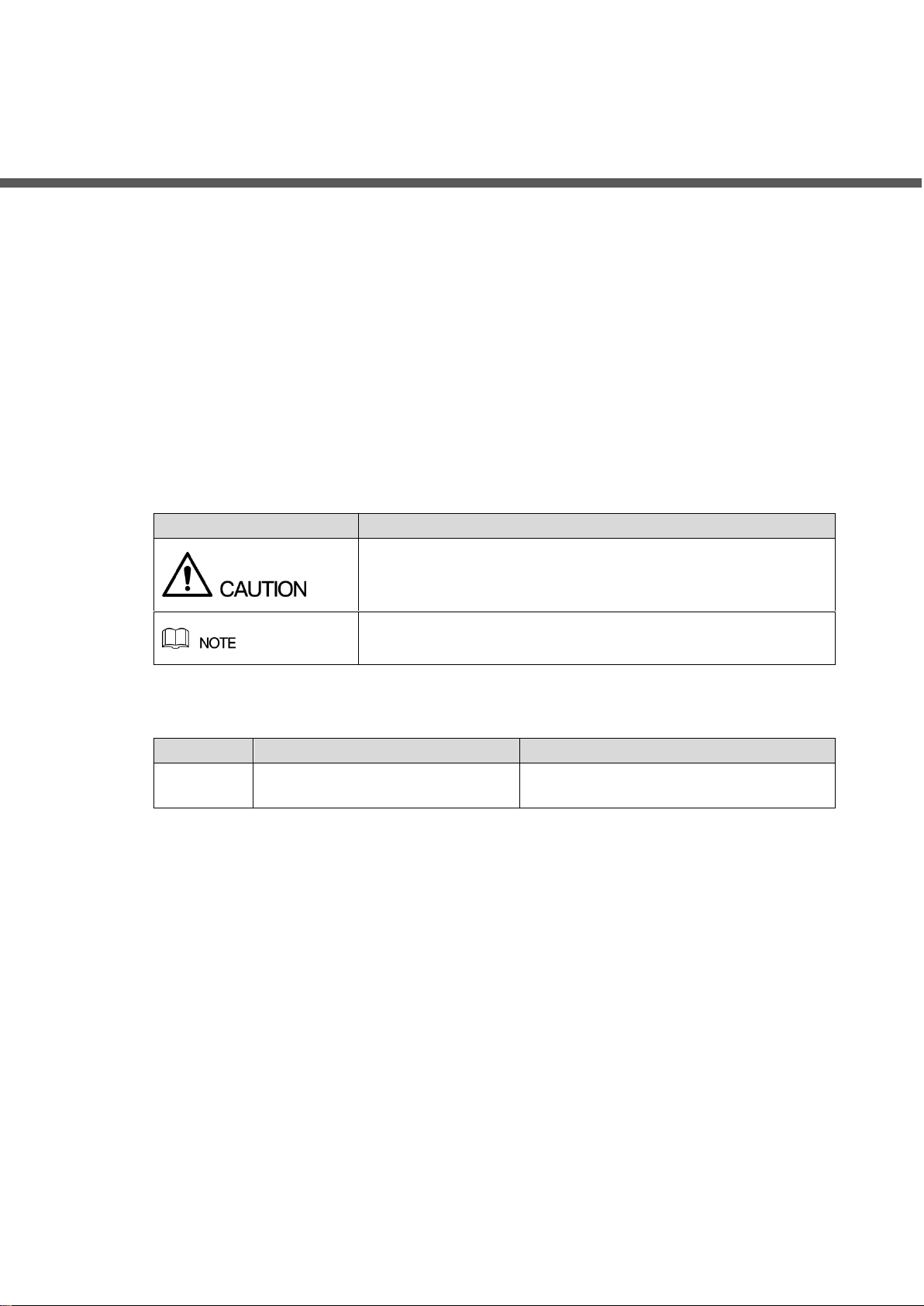
The following categorized signal words with defined meaning might appear in the manual.
Signal Words
Meaning
Indicates a potential risk which, if not avoided, may result in
property damage, data loss, lower performance, or
unpredictable result.
Provides additional information as the emphasis and
supplement to the text.
Revision History
Version
Revision Content
Release Time
V1.0.0
First release.
August 2019
Privacy Protection Notice
As the device user or data controller, you might collect personal data of others such as face,
fingerprints, car plate number, Email address, phone number, GPS and so on. You need to be
in compliance with the local privacy protection laws and regulations to protect the legitimate
rights and interests of other people by implementing measures include but not limited to:
providing clear and visible identification to inform data subject the existence of surveillance
area and providing related contact.
About the Manual
The manual is for reference only. If there is inconsistency between the manual and the
actual product, the actual product shall prevail.
We are not liable for any loss caused by the operations that do not comply with the manual.
The manual would be updated according to the latest laws and regulations of related
regions. For detailed information, see the paper manual, CD-ROM, QR code or our official

Foreword II
website. If there is inconsistency between paper manual and the electronic version, the
electronic version shall prevail.
All the designs and software are subject to change without prior written notice. The product
updates might cause some differences between the actual product and the manual. Please
contact the customer service for the latest program and supplementary documentation.
There still might be deviation in technical data, functions and operations description, or
errors in print. If there is any doubt or dispute, please refer to our final explanation.
Upgrade the reader software or try other mainstream reader software if the manual (in PDF
format) cannot be opened.
All trademarks, registered trademarks and the company names in the manual are the
properties of their respective owners.
Please visit our website, contact the supplier or customer service if there is any problem
occurred when using the device.
If there is any uncertainty or controversy, please refer to our final explanation.

Important Safeguards and Warnings III
Important Safeguards and Warnings
Operation Requirement
Do not place or install the Device in a place exposed to sunlight or near the heat source.
Keep the Device away from dampness, dust or soot.
Keep the Device installed horizontally on the stable place to prevent it from falling.
Do not drop or splash liquid onto the Device, and make sure there is no object filled with
liquid on the Device to prevent liquid from flowing into the Device.
Install the Device in a well-ventilated place, and do not block the ventilation of the Device.
Operate the device within the rated range of power input and output.
Do not dissemble the Device.
Transport, use and store the Device under the allowed humidity and temperature
conditions.
Electrical Safety
Improper battery use might result in fire, explosion, or inflammation.
When replacing battery, make sure the same model is used.
Use the recommended power cables in the region and conform to the rated power
specification.
Use the power adapter provided with the Device; otherwise, it might result in people injury
and device damage.
The power source shall conform to the requirement of the Safety Extra Low Voltage (SELV)
standard, and supply power with rated voltage which conforms to Limited power Source
requirement according to IEC60950-1. Please note that the power supply requirement is
subject to the device label.
Connect the device (I-type structure) to the power socket with protective earthing.
The appliance coupler is a disconnection device. When using the coupler, keep the angle
for easy operation.

Table of Contents IV
Table of Contents
Foreword.................................................................................................................................................... I
Important Safeguards and Warnings.................................................................................................... III
1 Checklist................................................................................................................................................. 1
Package........................................................................................................................................ 11.1 Port Definition................................................................................................................................ 11.2 1.2.1 Front Panel ......................................................................................................................... 1
1.2.2 Rear Panel.......................................................................................................................... 2
Device Installation......................................................................................................................... 21.3
2 Local Application................................................................................................................................... 3
FunctionArchitecture.................................................................................................................... 32.1 Business Configuration................................................................................................................. 42.2 2.2.1 Basic Setting....................................................................................................................... 4
2.2.2 Network Setting .................................................................................................................. 4
Operation Management................................................................................................................ 72.3 2.3.1 Operation Analysis.............................................................................................................. 7
2.3.2 System Management.......................................................................................................... 7
3 Configuring System.............................................................................................................................. 9
Cybersecurity Recommendations................................................................................... 10Appendix 1

Checklist 1
1 Checklist
Package1.1
Open the product package and then check if the product is damaged or missing.
Package: Product unit appearance is complete without obvious damage; after package is
opened, check if accessories and HDD are complete.
Device: Product unit appearance has no scratch, damage, and protection cover has no
obvious damage.
Accessories: Type and quantity in product checklist are correct and complete. Actual
accessories have no damage.
Table 1-1 Packing list
No.
Checklist
Quantity
Description
1
Server
1
–
2
Anti-vibration Screw for Hard
Drive
12
–
3
Anti-vibration Mat
12
–
4
Power Cable
1
1.5 m
5
Quick Start Guide
1
–
Port Definition1.2
Product front panel is equipped with power button, USB port and status indicators; rear panel is
equipped with a single power, Ethernet port, serial port and other ports.
1.2.1 Front Panel
Figure 1-1 Front panel
Table 1-2 Description
No.
Item
Description
1
Network Indicator
The light flashes blue when network is connected.
2
Alarm Indicator
The light flashes blue when device triggers alarm.
3
HDD1
System disk indicator. It flashes when reading disk.
4
HDD2
Hard drive indicator. It is normally on when hard drive is

Checklist 2
No.
Item
Description
5
HDD3
inserted.
6
HDD4
7
USB 2.0 Port
2 ports, white
8
Power Button
Press the button to start the device. The device is equipped
with power status indicator (blue normally on); long press it
to shut down the server.
1.2.2 Rear Panel
Figure 1-2 Rear panel
Table 1-3 Description
No.
Item
Description
1
Alarm Output
and Input
Reserved. Supports RS–485 protocol access.
2
Ethernet Port
Supports 10Mbps/100Mbps/1Gbps self-adaptive dual full
duplex. The platform default Ethernet port is 1.
3
Audio Output
3.5 mm audio output.
4
Audio Intercom
Input
3.5 mm audio input.
5
HDMI Port
2 channels, reserved.
6
VGA Port
DB 15 pin. Supports VGAport device access.
7
eSATA Port
Supports eSATA device access.
8
RS–232
Debugging serial port.
9
Single Power
AC 100V - 240V/47 - 63Hz; supports hot plug.
Device Installation1.3
Connect cables according to port introduction, and then connect the server to power.

Local Application 3
2 Local Application
Function Architecture2.1
The chapter introduces the functions of local application. See Figure 2-1. The local interface will
be displayed after starting the server. See Figure 2-2.
Local applicationFigure 2-1
Local
Local
Basic
Basic
Network
Network
Analysis
Analysis
System
System Reboot
Reboot
Shut down
Shut down
Password
Password
Reset
Reset
Reset Firewall
Reset Firewall
Version
Version
Server Detection
Server Detection
Network Detection
Network Detection
HDD Detection
HDD Detection
Environment Detection
Environment Detection
Network Mode
Network Mode
Network Info
Network Info
Time Setting
Time Setting
Standby
Standby
Local interfaceFigure 2-2

Local Application 4
Business Configuration2.2
2.2.1 Basic Setting
Click Basic Setting on the local interface, and then configure time and other settings.
Basic settingFigure 2-3
Table 2-1 Basic setting parameters description
Parameter
Description
System Time
Keep it the same as local time.
Date Format
Set data and time format of local application homepage.
Date Separator
Time Format
Device Name
It is the current product model name by default.
Standby Time
The server will get into standby mode when there is no operation for
several minutes. Set the threshold here. The default threshold value is
5 minutes; the maximum value is 15 minutes.
2.2.2 Network Setting
Click Network Setting on the local interface to display enter the network setting interface.

Local Application 5
Network settingFigure 2-4
Otros manuales para DSS4004-S2
2
Tabla de contenidos
Otros manuales de Servidor de Dahua

Dahua
Dahua EVS50 Series Manual de usuario

Dahua
Dahua IVSS Manual de usuario

Dahua
Dahua IVSS Manual de usuario

Dahua
Dahua EVS50 Series Manual de usuario

Dahua
Dahua DH-IVS-IP8000-E-GU1 Manual de usuario

Dahua
Dahua DSS4004-S2 Manual de usuario

Dahua
Dahua 8-HDD Series Manual de usuario

Dahua
Dahua EVS50 Series Manual de usuario


