Curtis 1ACUNIT-G2 Manual de instalación y funcionamiento

1 OF 114
SERVICE & REPAIR MANUAL
Air Conditioner
p/n: 1ACUNIT-G2
Service and Repair Manual
Approximate Installation Time *
Experienced Dealer Technician – 1 Hour
Average Dealer Technician – 1.5 Hours
Do-It-Yourself – 2 Hours
Product Specifications
25” x 36” x 7”
Weight: 53 lbs.
Air Flow: 306 CFM
Cooling Capacity: 12,000 BTU / hr
Voltage: 12 VDC
Amp Draw: 62
Refrigerant: R134a, 2.1 lbs. charge
Rev. A
p/n: RM-1ACUNIT-G2
This service manual is intended for use by only properly certified and trained technicians. Refrigeration systems
must only be serviced by individuals meeting all local, state and federal requirements

2 of 114
TABLE OF CONTENTS
Section Page
1. HOW TO USE THIS MANUAL…………………………………………..….3
2. WARNINGS……….………………………………………………….….....4-6
3. TECHNICIAN REQUIREMENTS…………………………………………...7
4. TECHNICAL OVERVIEW……………….…………...........................…....8
5. SPECIFICATIONS……………...…………………………………..….…....9
6. FEATURES & OPERATION ………………………………………..….....10
7. CARE AND MAINTENANCE………..……………………………..….…..10
8. REFRIGERANT FLOW DIAGRAM…………………………………….….11
9. BASIC TROUBLESHOOTING…………………...………………………..12
10. COVER & SEAL…….…………….………………………...……….….13-14
11. CONDESNER FAN……..……..…………………….………………....15-18
12. CONDENSER FAN BRACKET…………………..........................……..19
13. REFRIGERANT EVACUATION, VACCUM & CHARGE……….…..20-21
14. CONDENSER…….………………………….……….…………………....22
15. PRESSURE SWITCH…….……………………..…..……………...…23-24
16. RECEIVER/DRIER……...…………………...………………………...25-28
17. COMPRESSOR…….………….……………………………………....29-52
18. EVAPORATOR BOX……..………………………………..………….. 53-75
19. EVAPORATOR CORE…….……………………….…………………..76-95
20. THERMOSTAT…….…………………….……………………………...96-97
21. EXPANSION CONTROL VALVE………………………….…………98-104
22. WIRE HARNESS…………………………………………….……………105
23. COMPRESSOR SWITCH………………………….…….…………106-107
24. BLOWER SWITCH………………………………………….…………....108
25. WIRING SCHEMATIC……………………………………………………109
26. ELECTRICAL CIRCUIT OPERATION…………………….……….110-111
27. SERVICE PARTS…………………….………………………………112-114

3 of 114
1. HOW TO USE THIS MANUAL
Included in the first 11 pages of this manual are the operator instructions and service items.
Starting on page 12 are technical service and repair procedures.
All repair work instructions in this manual are to be done with the A/C unit removed from the
vehicle. See appropriate vehicle specific installation instructions for removal procedures. Any
service or repair procedure done with the A/C unit installed on the vehicle should be done
with the vehicle battery disconnected with the exception of specific troubleshooting
procedures as noted.
The installation and removal instructions are in an order that builds on themselves, by
section. I.E. when removing the condenser fan, first the condenser must be removed from
above the fan. That step is described along with assembly instructions. If you need to remove
the fan, use the condenser removal instruction, then the fan removal instruction. To install,
install the last component removed first (fan) then follow the next removed part (condenser)
installation instructions. Complex operations such as compressor removal have removal and
installation procedures listed in order by page as noted.
There are tips and cautionary notes included throughout this manual. Read the instructions
and review all notes on the pages before beginning work. Notes in RED are critical points
called out for safety as well as procedures that must be followed to successfully service and/
or repair the unit.
At the top of each page in the left hand corner are two notations. One is a diagram that
depicts the skill level of the technician required to safely and legally complete each task.
Please review the key for this depiction on page 7 of this manual. The second is a list of tools
required to complete the tasks listed on that page.
There are notes on each page containing an operation that requires the technician to have
certification meeting Part 609 EPA standards. Following these guides is imperative for the
technician’s safety and compliance with EPA laws. Technicians must also follow all Local,
State, and Federal guidelines for handling R134a refrigerant.
Pay close attention to notes contained in these sections

4 of 114
Curtis air conditioners feature an assembly of parts designed for your vehicle which require
adjustment and alignment of components to accommodate vehicle variations. For accurate
installation, proper operation, and years of satisfaction, please read and understand the
Service & Owner’s Manual fully prior to installing the air conditioner.
From all of us at Curtis, we thank you for choosing our product.
driver and passenger.
Curtis accessory weights are listed in product
add additional weight to the base vehicle. All
Curtis Cabs, blades and general accessories
ADDED
WEIGHT
brochures. Deduct the accessory's total weight
from the vehicle's rated capacity and never
exceed the vehicle's rated capacity including
Exposure to Carbon Monoxide can Cause illness, seri-
ous injury or death. Never operate vehicle if suspicious
of Carbon Monoxide. Inspect exhaust system for leaks
monthly. Leaks can result from loose connections, corro-
sion, cracks or other damage to the exhaust manifold. If
leaks are found, repair or replace exhaust system. Do not
use vehicle until repair or replacement is complete.
2. WARNINGS
HELPFUL HINTS:
• Read and understand all instructions before beginning.
• Apply a silicone sealant to seal any minor gaps that may occur due to vehicle variations.
• Use caution to avoid damaging installed threaded inserts or weld nuts. Begin the thread engagement by hand to avoid
or correct potential cross threading.
• Plastic washers have been supplied to provide a weather seal under the heads of some exterior bolts. The plastic
washer should be installed under each bolt head directly against the outside cab surface. Care should be taken not to
over tighten the fasteners and damage the plastic washer.
• Silicone, Epoxy, Cork Tape, industrial hot melt glue, high adhesion duct work tape are used in sealing air, water drains,
and preventing moisture build-up on internal components. Be sure to replace any of these sealants and/or fasteners
when servicing or replacing components. Failure to properly install these components can result in performance
degradation and damage to the components.
GENERAL INFORMATION BEFORE YOU START
California Health and Safety Proposition 65 Warning: This product may contain
chemicals known to the state of California to cause cancer and birth defects or other repro-
ductive harm.
Shock Hazard: Always disconnect the negative lead of the battery before servicing.
Disclaimer: Always discharge air conditioner refrigerant in accordance with all federal,
state, and local laws.
System evacuation and charging must only be performed by an EPA Part 609 certified technician,
using EPA certified refrigerant handling equipment suitable for R134a refrigerant. Both the technician
and equipment must meet all State, Local and Federal requirements. R134a refrigerant is under high
pressure and when released can cause severe bodily harm including from contact risk of localized
frost bite. Always wear proper personal safety equipment when working on refrigerant system includ-
ing safety glasses and gloves. Follow refrigerant recovery equipment manufacturer’s safety and oper-
ation guidelines for use of their equipment. Only perform service in a well ventilated area away from
contamination and sources of ignition. Never pressurize system with compressed air to perform a leak
check. R134a refrigerant can become flammable and could explode under certain conditions.

5 of 114
2. WARNINGS
The air conditioner should arrive laying down flat.
Take care to protect the switches and louvers at the bottom of
the unit when handling.
Do not tip the air conditioner more than 15° in the direction
shown above during installation and service.
Doing so will drain the oil from the compressor.
Do not receive the air conditioner from the shipping
company if the air conditioner is standing up on end as
shown.
Doing so will drain the oil from the compressor.
15° MAX
Do not tip the air conditioner more than 90° in the
direction shown above during installation and service.
Doing so will drain the oil from the compressor.
** NOTE THIS IS THE ONLY DIRECTION THE AIR
CONDITIONER CAN BE TILTED TO 90 DEGREES
90° MAX THIS
DIRECTION
ONLY

6 of 114
2. WARNINGS
Do not tip the air conditioner more than 30° in the direction
shown above during installation and service.
Doing so may drain the oil from the compressor.
30° MAX
Do not tip the air conditioner more than 30° in the
direction shown above during installation and service.
Doing so may drain the oil from the compressor.
30° MAX

7 of 114
OPERATION TO BE PERFORMED BY AN EPA PART 609 CERTIFIED TECHNICICAN THAT HAS
BEEN SPECIFICALLY TRAINED & LICENCED IN R134a REFRIGERANT AIR CONDITIONER
EVACUATION, SERVICE, AND REPAIR USING EPA CERTIFIED EQUIPMENT
OPERATION TO BE PERFORMED BY AN EPA PART 609 CERTIFIED TECHNICICAN THAT HAS
BEEN SPECIFICALLY TRAINED & LICENCED IN R134a REFRIGERANT AIR CONDITIONER
EVACUATION, SERVICE, AND REPAIR USING EPA APPROVED EQUIPMENT OR BY A QUALIFIED
TECHNICIAN THAT IS UNDER CLOSE SUPERVISION OF AN EPA PART 609 CERTIFIED
TECHNICIAN THAT HAS BEEN SPECIFICALLY TRAINED & LICENCED IN R134a REFRIGERANT
AIR CONDITIONER EVACUATION, SERVICE, AND REPAIR USING EPA APPROVED EQUIPMENT
OPERATION TO BE PERFORMED BY QUALIFIED TECHNICIAN
3. TECHNICIAN REQUIREMENTS
PLEASE FAMILIARIZE YOURSELF WITH THE FOLLOWING TECHNICIAN REQUIRED
QUALIFICATION DIAGRAMS AND DESCRIPTIONS.
DIAGRAMS ARE LOCATED ON EACH PAGE AT THE TOP LEFT HAND CORNER AS A
REFERENCE TO THE SKILL LEVEL AND QUALIFICATION REQUIRED FOR A TECHNICIAN TO
SAFELY AND LEGALLY PERFORM THE TASK ON THAT PAGE. FAILURE TO FOLLOW THESE
GUIDELINES COULD RESULT IN INJURY AND/OR DEATH, DAMAGE TO PROPERTY, AND
VIOLATION OF LOCAL, STATE, AND FEDERAL LAWS
1
23
1
2
3
1
2
3

8 of 114
4. TECHNICAL OVERVIEW
The Curtis A/C unit (p/n: 1ACUNITG-2) is an all electric driven system that has a 12 volt electric
scroll compressor and utilizes R134a refrigerant.
The system is assembled from standard automotive grade components, with a Tube and Fin
Evaporator and a Bar & Plate Condenser.
The refrigerant system is regulated by an Electronic Thermostat as well as an Expansion Control
Valve (ECV).
Due to the Electric Compressor being located in the roof top unit, there are no refrigeration lines
being subjected to engine vibrations and heat loads. Also, unlike a standard automotive
mechanical compressor, the electric compressor has no rotating parts exposed to the
atmosphere, thus eliminating a common leak point.
With the refrigerant system being completely contained within the Roof Top Unit, it can be
shipped fully charged with refrigerant (within the continental US).
As part of Curtis’s Quality Control Process, each unit is leak and performance tested on a Run
Bench.
Due to the robust self contained design, the Curtis G2 Roof Top A/C unit requires very little
maintenance. The only items requiring scheduled maintenance within the unit are the Evaporator
drain tubes and condenser core, which require being cleared of any blockage, debris and/or
insects. Curtis recommends the operator inspect all fasteners every 40 hours to assure they
remain tight due to the off road use of the vehicle.
*As with any R134a refrigeration system, it is mandatory that only a trained and properly
qualified/ licensed technician perform any service or repair requiring removal and replacement
of refrigerant to the system using certified Recovery, Recycle and Charging equipment.

9 of 114
5. SPECIFICATIONS
WEIGHT: 53LBS (A/C UNIT WITH COVER)
HEIGHT ABOVE CAB: 3-5/8”
INTRUSION INTO CAB: 2” (OPERATOR AREA); 3” (LOWEST POINT)
SYSTEM : 12V DC
RUNNING AMPERAGE DRAW: 62 AMP (HIGH BLOWER SPEED)
HOUSING: POWDER COATED, CORROSION RESISTANT ALUMINUM ALLOY
COVER: POWDER COATED, CORROSION RESISTANT ALUMINUM ALLOY
EVAPORATOR CORE: AUTOMOTIVE GRADE, CORROSION RESISTANT ALUMINUM ALLOY, TUBE AND FIN
CONDENSER CORE: POWDER COATED, CORROSION RESISTANT ALUMINUM ALLOY, BAR AND PLATE
EVAPERATOR BLOWER: 306CFM AUTOMOTIVE GRADE 12 VOLT, 10 AMP WITH 3 SPEEDS
CONDENSER FAN: AUTOMOTIVE GRADE, 12 VOLT, 20 AMP, LOW NOISE, “S” BLADED
INTAKE: INTEGRATED INTO CASE, SINGLE POINT ENTRY, RECIRCULATION, NON FILTERED
OUTLET: FOUR 4-WAY ADJUSTABLE LOUVERED VENTS
OPERATOR CONTROLS: COMPRESSOR ON/OFF, SYSTEM ON/OFF WITH 3 BLOWER SPEEDS, ON SELECT
VEHICLES ALTERNATOR BY-PASS BUTTON
LOAD CONTROL: PATENTED ELECTRONIC AUTOMATED CONTROL OF ALTERNATOR LOAD ON ENGINE
THERMOSTAT: ELECTRONIC, THERMISTOR SENSOR, NON-ADJUSTABLE
REFRIGERANT: 2.1 LBS R134a
REFRIGERANT OIL: 3 OZ ZEROL ESTER 68SL
COOLING CAPACITY: 12,000 BTU / HR
10 of 114
7. CARE AND MAINTENANCE
• Clean the exterior of the condenser after every 50 hours of operation, or as needed depending on usage
conditions.
• Periodically inspect and tighten hardware after every 40 hours of operation for the entire life of the air
conditioner.
• Wash the painted surfaces of the air conditioner with commercial automotive cleaning products.
• Every 3 months of use, or annually, assure the Evaporator Drain Tubes are clear of blockage & draining
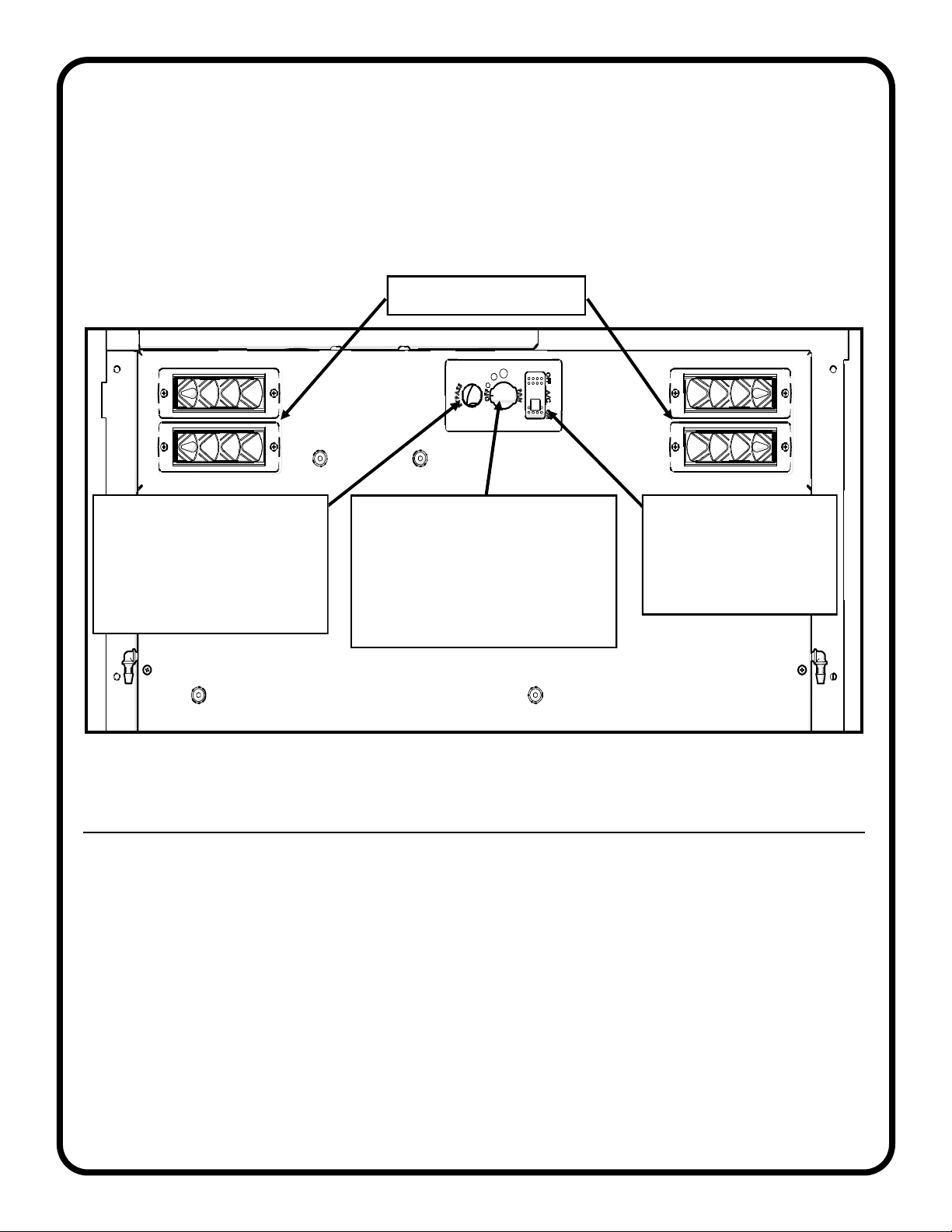
6. FEATURES & OPERATION
Turn the 4-POSITION FAN CONTROL SWITCH to activate the blower. The air conditioner may be used as a
fan in this manner.
Toggle the A/C ON-OFF SWITCH to activate the compressor for chilled air. The blower must be turned on
before the compressor will activate.
4 louvered vents are adjustable for air direction and volume
4-POSITION FAN CONTROL SWITCH
OFF-LOW-MED-HIGH
CONTROLS THE BLOWER FAN AND
MUST BE ON FOR THE
COMPRESSOR SWITCH TO
OPERATE.
A/C ON-OFF SWITCH
BLUE L.E.D. TURNS ON
WHEN A/C COMPRESSOR
IS SWITCHED TO ON
POSITION.
ALTERNATOR BYPASS BUTTON
OR PLUG (MODEL DEPENDENT)
WHEN USED TURNS THE
ALTERNATOR LOAD OFF
MOMENTARILY FOR ADDITIONAL
POWER WHEN REQUIRED.
Adjustable louvered vents
Tabla de contenidos
Otros manuales de Acondicionador de aire de Curtis


