Crestron CAGE2 3-Card Expansion Cage for AV2
Leading Specifications
The table below provides a summary of leading specifications for the CAGE2.
Dimensions and weight are rounded to the nearest hundredth unit.
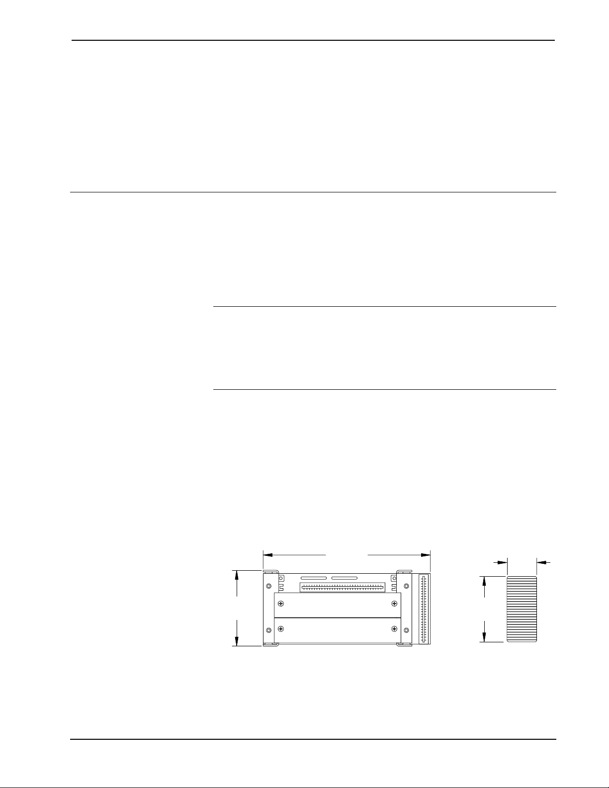
Leading Specifications of the CAGE2
SPECIFICATION DETAILS
SIMPL™ Windows®Version 2.00 or later 1
2-Series Control System Update File 2Version 1.000.CUZ or later 3
Dimensions & Weight Height: 3.00 in (7.62 cm)
Width: 6.60 in (16.77 cm)
Depth: 7.12 in (18.08 cm)
Weight: 11.70 oz (0.36 kg) 4
1 The latest software versions can be obtained from the What’s New page (SIMPL
Windows section) or Downloads page (SIMPLWIN Library) of Crestron’s website
(www.crestron.com). New users are required to register in order to obtain access to the
FTP site.
2 Crestron 2-Series control systems include the AV2, AV2 with Card Cage, CP2, CP2E,
PAC2, PAC2M, PRO2, and RACK2.
3 Filenames for 2-Series control system update files have a CUZ extension and can be
obtained from the What’s New page (Control Systems Update Files section) or
Downloads page (OPSYS Library) of Crestron’s website.
4 The listed weight includes the CAGE2, two blank faceplates and PCB interconnect
jumper.
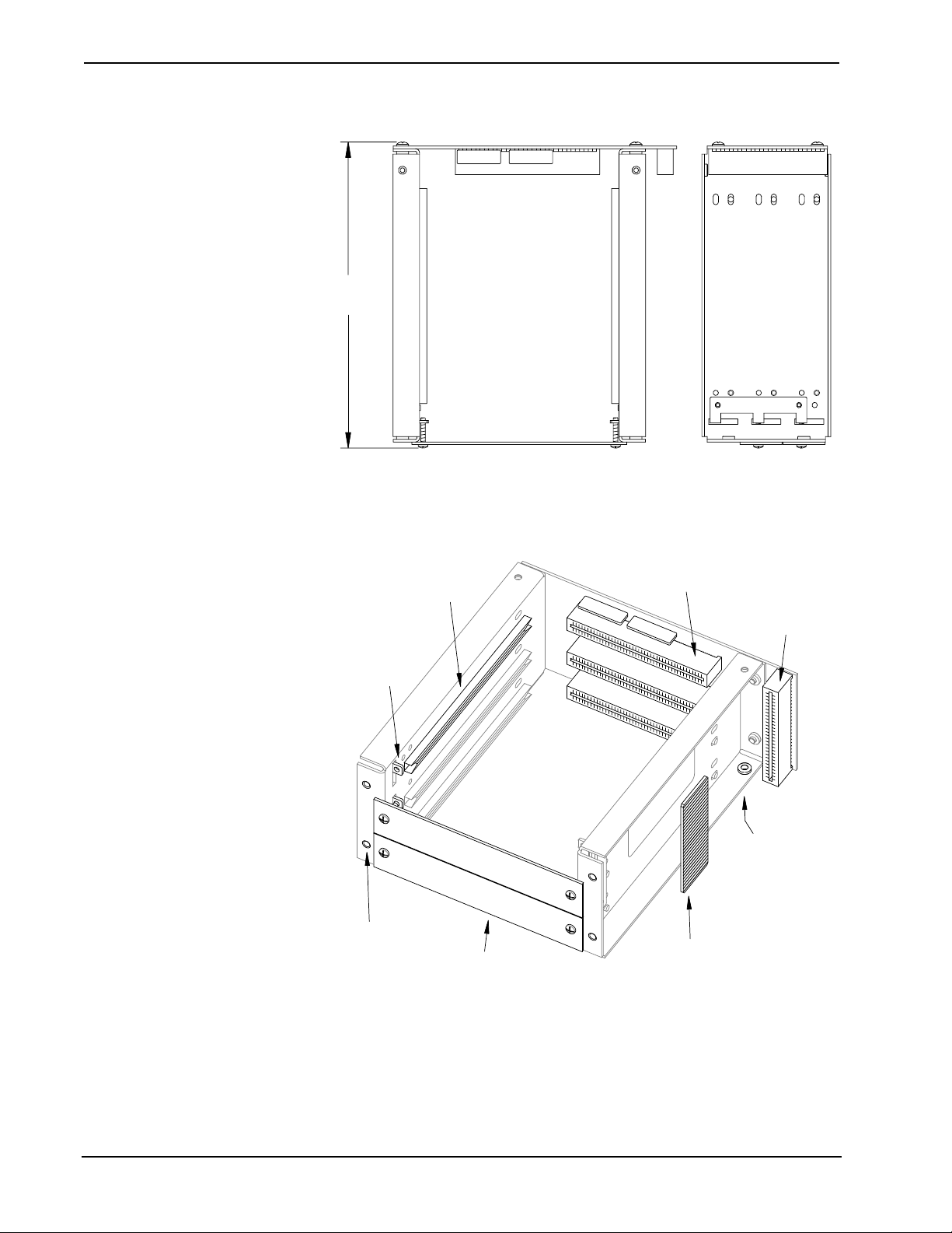
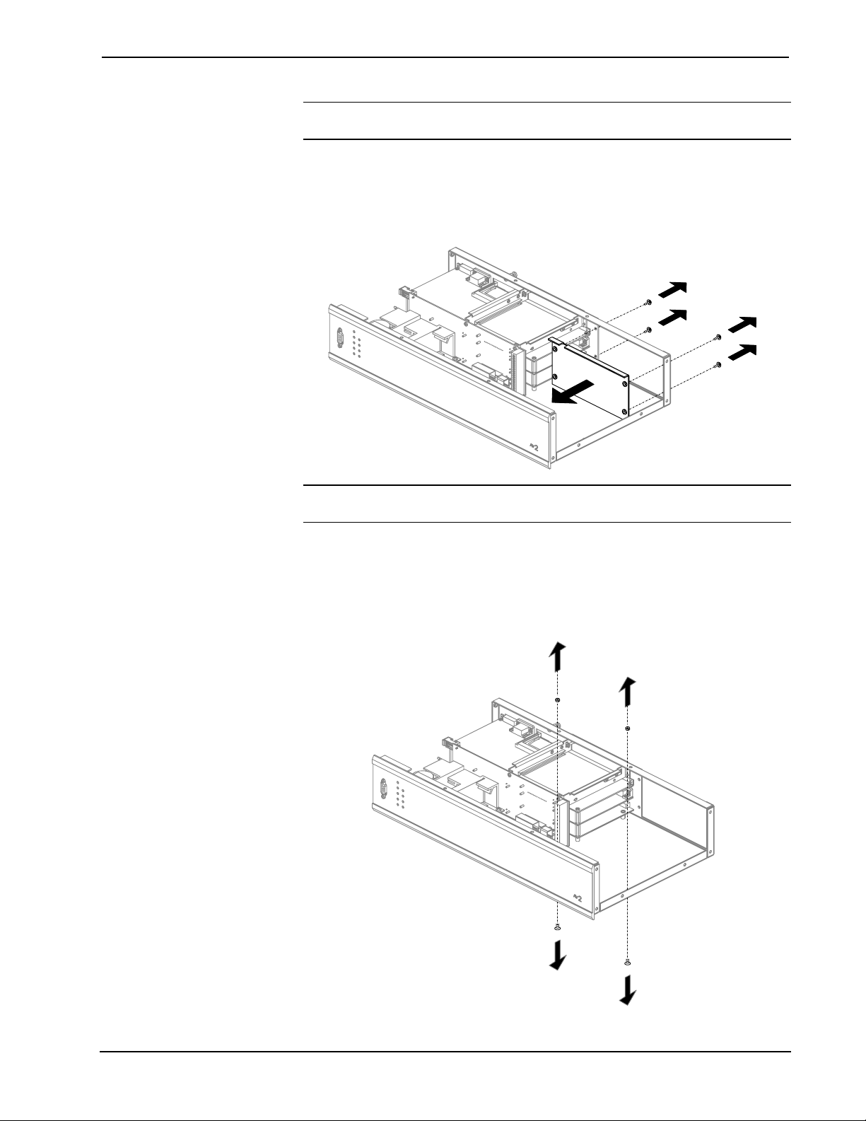
Installation
The tools required for installation are a #2 Phillips tip screwdriver, a 1/4-in nut
driver or wrench, and a grounding strap. Follow the procedure after this paragraph.
CAUTION: The AV2 contains electro-static discharge (ESD) sensitive devices.
Perform the following procedure while wearing a grounding strap that is properly
grounded or on a grounded workstation to avoid damaging the AV2.
CAUTION: To prevent stripping of screw heads, threads, or mounting holes, do
not overtighten screws. Tighten only to the specification listed in the individual
step(s).
NOTE: Due to the different interconnect connectors, the CAGE2 and CNXCAGE
are not interchangeable. Do not attempt to install a CNXCAGE into the AV2.
NOTE: During this installation procedure, all screws removed from the AV2 must
be retained to install the CAGE2.
NOTE: It is assumed that the AV2 rack ear brackets are not attached and power has
been disconnected during this installation procedure.
Installation Guide - DOC. 5964 3-Card Expansion Cage for AV2: CAGE2 •3