Craft CHAMP Manual de usuario

WWW.CRAFT-INC.COM
Visit our YouTube channel - Link can be found on our website
TELEPHONE # 508-761-7917
TOLL FREE WITHIN THE UNITED STATES 1-800-8-CRAFT-8
CHAMP TOGGLE PRESS INSTRUCTIONS
Craft Inc., founded in 1950, has been a pioneer in self-fastening hardware for the photo frame
and framed picture industry. Our 4th generation CHAMP is a simple, compact machine with
changeable fixtures that make it possible to install a variety of Craft’s self-fastening hardware
quickly, economically and effectively. Reading and following the instructions carefully will
enable you to get the most from your CHAMP machine.

CONTENTS
-Unpacking
-Assembly of Base Machine Toggle Press
-Easel Hinges
oEasel Hinge Kit
oInstalling the Disc
oInstalling the Hinge Application Head
oInstalling the Easel Locating Corner Fixture
-Hangers
oHanger Kit
oInstalling the Kit
oInstalling the Hanger Application Head
oInstalling the Stop Kit
-Adjusting and Hardware Installation
oAdjusting the Easel Hinge Disc and Locating Fixture / First Hinge Installation
oInstalling Easel Hinges
oAdjusting for Hanger Application with Side and Back Stops / First Hanger Installation
oInstalling Hangers
-Shear Screw
-Lubrication Chart
UNPACKING
1. Remove all packing material until you can see the CHAMP machine.
2. Remove all component Bags and set aside
3. Remove the left and right side Table Arms along with the CHAMP Main Frame
4. Lay out any remaining items from the box.

ASSEMBLY OF BASE MACHINE TOGGLE PRESS –(# CHAMP4-00)
1. Place the CHAMP Main Frame on flat work surface with Toggle Mechanism facing the assembler.
2. Raise the Toggle Mechanism using the Toggle Handle with blue grip to retract the Toggle Mechanism.
This will give the assembler some room to work.
3. Place the side Table Arms on each side of the CHAMP as shown.
4. Locate the (4) M6 socket head cap screws sealed in one of the bags from the shipping box. Use (2) of
these screws, and the 5mm long handled wrench provided to fasten the left side Table Arm into the Base
Frame Nuts as shown. Before tightening, locate the “SET UP” line to insure proper location of the Table
Arm.

5. Repeat Step 4 for the right side Table Arm
6. The CHAMP is designed to be fastened down to a sturdy work surface for operator safety and also correct
application of the self-fastening Craft hardware.
You have now completed assembly of the CHAMP Base Machine Manual Toggle Press
EASEL HINGES
If there is a previously installed Apply Head and / or Disc, please remove them from the CHAMP
Machine before continuing.
EASEL HINGE KIT - (# CHAMP4-GUID-30)
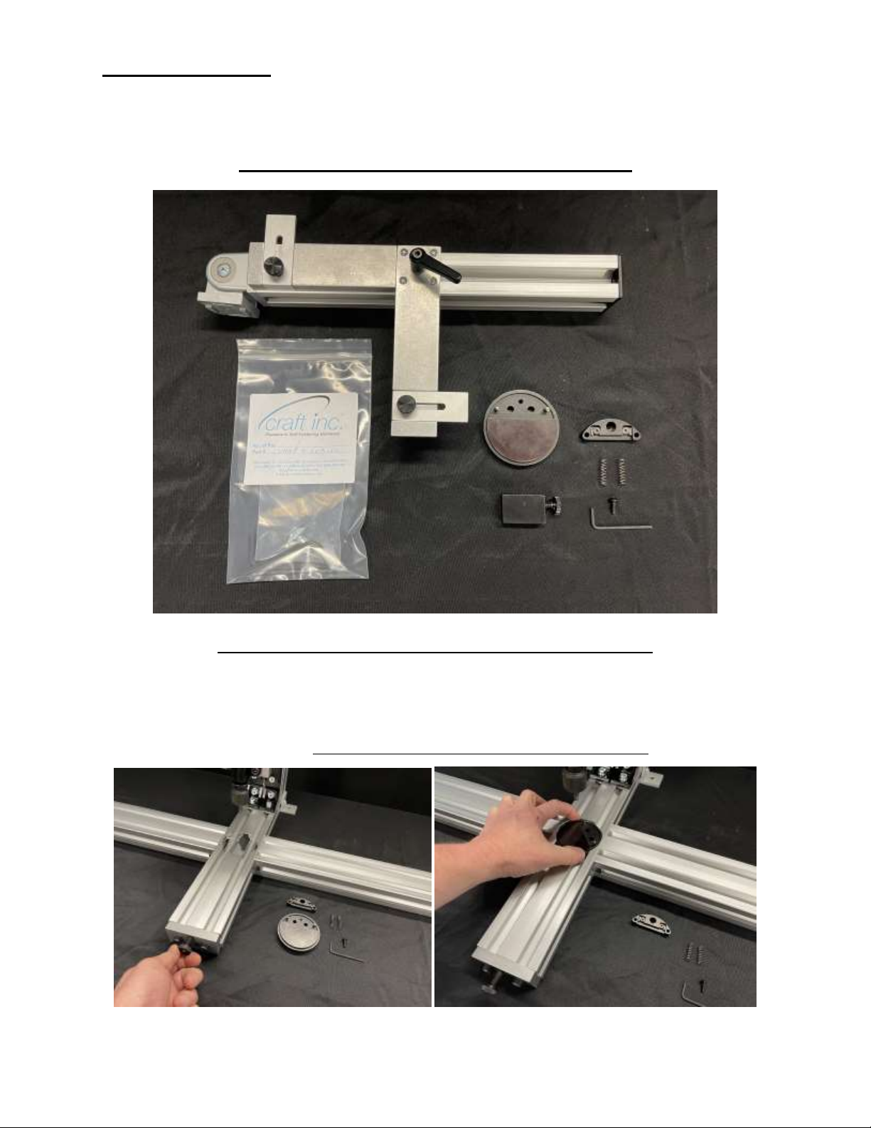
INSTALLING THE DISC - (# CHAMP4-DISC-04)
1. Turn the Disc Clamp Threaded Rod with the End Cap attached counter clockwise to back the Rod out.
Make sure that the Rod is not visible in the Disc area. This will allow the Disc to easily drop into its
correct location.
2. Place the Disc, facing up, into the Base of the CHAMP as shown. You will notice that the fit is close but
you can still freely spin the Disc. DO NOT RE-TIGHTEN THE THREADED ROD YET.

INSTALLING THE HINGE LOCATOR
# CHAMP4-LOC-31 –FOR THE 6239 OR 6241 CRAFT EASEL HINGE
# CHAMP4-LOC-32 –FOR THE 6229, 6232 OR 6234 CRAFT EASEL HINGE
1. Select your Easel Hinge Locator (One of your choice is supplied with Easel Hinge Kit)
2. Insert the (2) Coil Springs supplied with the Hinge Locator into receiver holes in the Disc.
3. Place Easel Hinge Locator over locating pins in the Disc while inserting the Button Head Screw supplied
with the Hinge Locator. Using the Hex Key Wrench supplied, rotate the Button Head Screw clockwise.
(Tightening or loosening Button Head Screw compensates/adjusts for various board thickness by raising
or lowering the height of the Hinge Locator)
INSTALLING THE HINGE APPLICATION HEAD (# CHAMP4-HD-EASEL)
1. Slide the Hinge Applicator Head onto the Vertical Adjustment Knob as far as it will go and tighten the
Thumb Screw. (Do not over tighten)

INSTALLING THE EASEL LOCATING CORNER FIXTURE
1. From the bag inside the Kit, remove the 8mm Low Head Cap Screw along with the Spring Nut. Insert the
Spring Nut into the Left Side Table Arm as shown. With a flat screw driver or coin (not supplied), rotate
the nut 90° clockwise while slightly depressing the nut.
2. Mounting the Easel Locating Corner Fixture can now be accomplished by using the supplied 6mm Hex
Wrench along with the 8mm Low Head Cap Screw removed from the bar earlier. Simply place the Corner
Joint over the M8 nut inside the extrusion and utilize the locating pads. Screw the M8 Low Head Cap
Screw in almost all of the way…just enough to slide the Assembly over to its permanent location.

By loosening the Clamp Handle and also the Corner Joint (use supplied 4mm Hex Key Wrench), the
Corner Fixture can articulate for virtually any Easel shape.
You have now completed assembly of the CHAMP Base Machine Manual Toggle Press with the Easel
Hinge Attachment
HANGERS
If there is a previously installed Apply Head and / or Disc, please remove them from the CHAMP
Machine before continuing.
The Easel Locating Corner Fixture can remain on the CHAMP if you so choose while using the Hanger
Kit. We are showing the CHAMP with the Easel Hinge Kit entirely removed.
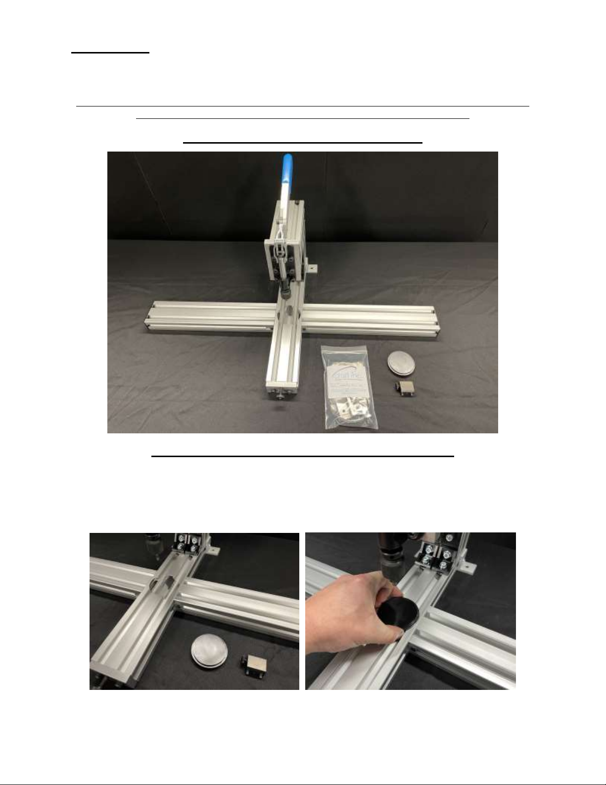
HANGER KIT - (# CHAMP4-GUID-40)
INSTALLING THE DISC - (# CHAMP4-DISC-03)
1. Turn the Disc Clamp Threaded Rod with the End Cap attached counter clockwise to back the Rod out.
Make sure that the Rod is not visible in the Disc area. This will allow the Disc to easily drop into its
correct location.
2. Place the Disc, facing up, into the Base of the CHAMP as shown. You will notice that the fit is close but
you can still freely spin the Disc. Turn the End Cap and Threaded Rod until it firmly pushes against the
Disc. This will hold the Disc in place.

INSTALLING THE HANGER APPLICATION HEAD –
(# CHAMP4-HD-XXXX) THERE ARE SEVERAL TO SELECT FROM
1. Slide the Hanger Applicator Head onto the Vertical Adjustment Knob as far as it will go and tighten the
Thumb Screw. (Do not over tighten)
INSTALLING THE STOP KIT
From the bag inside the Kit, remove all of the items. There will be (2) 6mm x 14mm long Cap Screws, (1)
6mm x 20mm long Cap Screw,(3) Spring Nuts, (2) Side Stop Bars, (1) Back Stop Plate, (1)Right to Left
adhesive backed scale and (1) Left to Right adhesive backed scale and a 5mm Hex Key Wrench.
1. Insert the (3) Spring Nuts into the Base extrusion as shown. With a flat screw driver or coin (not
supplied), rotate the nuts 90° clockwise while slightly depressing the nut.
Tabla de contenidos
Otros manuales de Herramientas eléctricas de Craft


