
Cormach GEO 10 Manual de usuario
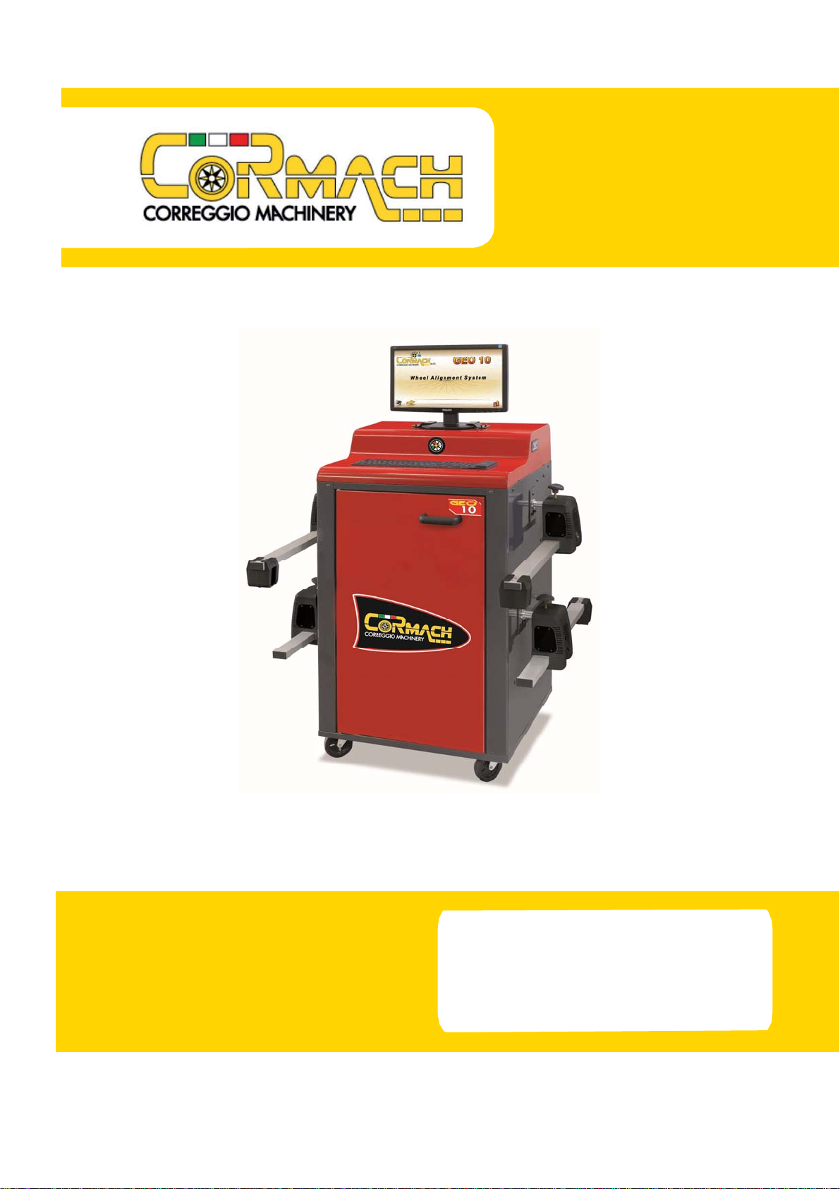
WHEEL ALIGNER
GEO 10
03/2014
SERVICE MANUAL UK


Technical service manual GEO 10 3
CONTENTS
INTRODUCTION............................................................................................. 4
TECHNICAL DATA.......................................................................................... 4
WHEEL ALIGNER COMPOSITION................................................................ 4
INSTALLATION............................................................................................... 4
CENTRAL UNIT............................................................................................... 7
BIOS CONFIGURATION SK INTEL D525MW............................................... 7
BIOS CONFIGURATION SK INTEL DG41RQ............................................... 8
WHEEL ALIGNER SOFTWARE...................................................................... 9
Instructions for changing the language settings ........................................10
ENABLING EXTRA WHEEL ALIGNER FUNCTIONS................................. 17
HEADS........................................................................................................... 19
CALIBRATION ............................................................................................... 21
UTILITY PROGRAMS ................................................................................... 24
SERVICE PROGRAM ................................................................................... 25
RADIO............................................................................................................ 27
INSTALLING THE DATABANK UPGRADE................................................. 31
INSTALLING THE SOFTWARE UPGRADE................................................. 31
GENERAL ELECTRICAL WIRING DIAGRAM (FIG.19) .............................. 35
All rights reserved. No part of this publication may be
translated, stored in an electronic retrieval system,
reproduced, or partially or totally adapted by any means (in-
cluding microfilm and photostats) without prior permission.
The information contained herein may be subject to modifi-
cations without prior notice.
English

4 Technical service manual GEO 10
INTRODUCTION
The purpose of this manual is to furnish instructions for the installation and maintenance of
the wheel aligner.
This manual is for use in addition to the User and Service Manual supplied with the
equipment, and does not cover the same topics.
TECHNICAL DATA
Refer to the User and Service Manual for the complete technical data of the aligner.
Special attention must be paid to the working ambient conditions in relation to the wheel
aligner’s configuration. Note that the temperature range of 5°C - 35°C is the maximum the
components are able to tolerate and outside the range 10°C - 30°C they may not perform to
the expected standards.
WHEEL ALIGNER COMPOSITION
The wheel aligner consists of a central unit and four measuring sensors to apply to the whe-
els of the vehicle.
The central unit consists of a cabinet containing the monitor, the keyboard, the printer, the
personal computer and the radio interface (for radio versions only). The personal computer
contains the electronics necessary for the wheel aligner to operate.
The four measuring sensors are fitted with microcontroller boards for full control of the
angle measuring sensors (infrared CMOS goniometers) and the electronic inclinometers for
measuring the camber and levelling the sensor.
INSTALLATION
Install the wheel aligner following the instructions in the operator’s manual. The electrical
connections between the various devices are shown in the electric system diagram (Fig.19).
CENTRAL UNIT
The central unit is the same for all versions of the wheel aligner.
Figures 1-2 show some details for correct laying of the wiring of the components which, for
reasons of transport, are supplied in their original packaging (such as the printer, the PC, the
keyboard and the monitor).
Ensure that all ground cables providing user protection, especially rear panel connections,
are connected at all times.
Connect the personal computer as described in the User and Service Manual.
The wheel aligner power supply cable must be connected to the connector provided (A,
Fig.1). Check the mains power supply data on the mains cable dataplate with care before
connecting the equipment. Reference should be made to the national regulations when
constructing the electrical system; the wheel aligner’s technical data are provided in the
User and Service Manual.
Technical service manual GEO 10 5
SIM CARDS
The aligner cannot be operated unless a hardware protection key has been inserted.
The main protection board configured for the basic version is supplied with the machine.
Additional functions can be added to the wheel aligner by installing the upgrade kits (see
the User and Service Manual).
Installing the Hard Lock device:
Insert the tip of a pen into the hole at the side to open the SIM holder (fig. 7).
Remove the wheel aligner SIM card (fig. 6) from its punched support (keep the support
with the serial number for future queries) and insert in the SIM holder (fig. 7), with the gold
contacts facing upward. Push the SIM holder in.
For the update procedure, refer to the User and Service Manual.
WHEEL ALIGNER SOFTWARE
The wheel aligner is supplied with the software already installed. The CD supplied car-
ries a copy of the software.
The program is installed in the C:\Program Files\Alignment\… folder.
When the equipment is switched on, the software release installed will be displayed
on the screen (centre left).
Compare this release with that stated on the installation CD-ROM supplied with the
aligner.
If the CD-ROM release is more recent than the release installed, upgrade the aligner
software.
Upgrading the wheel aligner software
The files which contain the translations of the program texts into foreign languages will
be found in the folder:
C:\PROGRAM FILES\ALIGNMENT\TEXT\
Each language has its own files in a specific sub-directory:
STRING.INI: contains all the texts of the icons and the program windows.
REGOLAZ.INI: the texts of the animations.
STRSETUP.INI: the texts of the user set-up.
STRSETUPA.INI: the texts of the after-sales service set-up.
The files which contain the foreign-language translations of the “On-line help” pages
are in the folder: C:\PROGRAM FILES\ALIGNMENT\HELP\.
•Quittheoperatingsystembyclickingthe icon and entering the password
“end” (in lower-case letters).
•InserttheCD-ROMinthedriveandwaitfortheupgradeinstallationprogramtorun
automatically.
•Selectthelanguagerequiredandproceedwiththeinstallationprocedure.
WARNING
Once the software has been installed, the PC restarts automatically.
6 Technical service manual GEO 10
RADIO HEADS
The radio heads kit consists of 4 sensors, the rechargeable NiMH batteries to power the
heads, and the radio set for the central unit.
The way a battery is charged for the first time affects its performance for the rest of its life.
For the best performance, consult the first charge instructions provided in the “Battery
Pack” section. In case of a radio communications malfunction, the ordinary head cables can
be used to connect the heads to the central unit.
ELECTRICAL CONNECTOR PANEL
Install the electrical connector panel at the bottom of the cabinet (A, Fig. 1).
Connect electrical connector panel to one of the HDD power cables leading out of the
back of the PC and to the Hard Lock device with a USB cable (G, F, fig. 2).
There are 2 LEDs (yellow and green) for each emergency cable connector.
The green LED lights up to indicate that power supply is on.
The yellow LED lights up to indicate that communication with the connected head has
been established successfully.
HARD LOCK
Fix the Hard Lock device (B, Fig. 3) and the 2 charging cable retainer brackets (A, Fig.
4) onto the back of the cabinet with the relative fastener screws. Connect the 2 USB
cables to the Hard Lock device. Connect the first one to an unused USB port on the PC.
Connect the second one to the USB port on the electrical connector panel (E, F, Fig. 2).
Connect the 4 sensor charging cables (with RJ45 connectors) to the electrical connector
panel (A, fig. 1) and fasten them into the 2 charging cable retainer brackets (A, Fig. 4) at
the back of the cabinet.
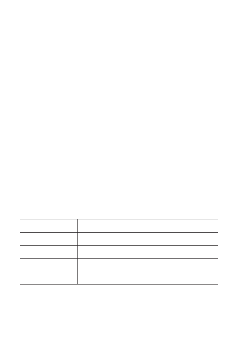
Two LEDs (a green and a yellow one) are located on the Hard Lock and are visible from
the outside:
Condition LED status
Aligner power-on Lamp Test of both LEDs.
Main SIM CARD present GREEN LED is lit up with a fixed light.
Remote control signal
reception
GREEN LED changes status upon receipt of input pulse from
remote control.
Radio communication
with heads YELLOW LED flashes in synch with communication.
Technical service manual GEO 10 7
CENTRAL UNIT
SK INTEL D525MW BIOS CONFIGURATION
The configuration outlined here refers to BIOS version MWPNT10N.8
6A.0074.2010.1217.1730
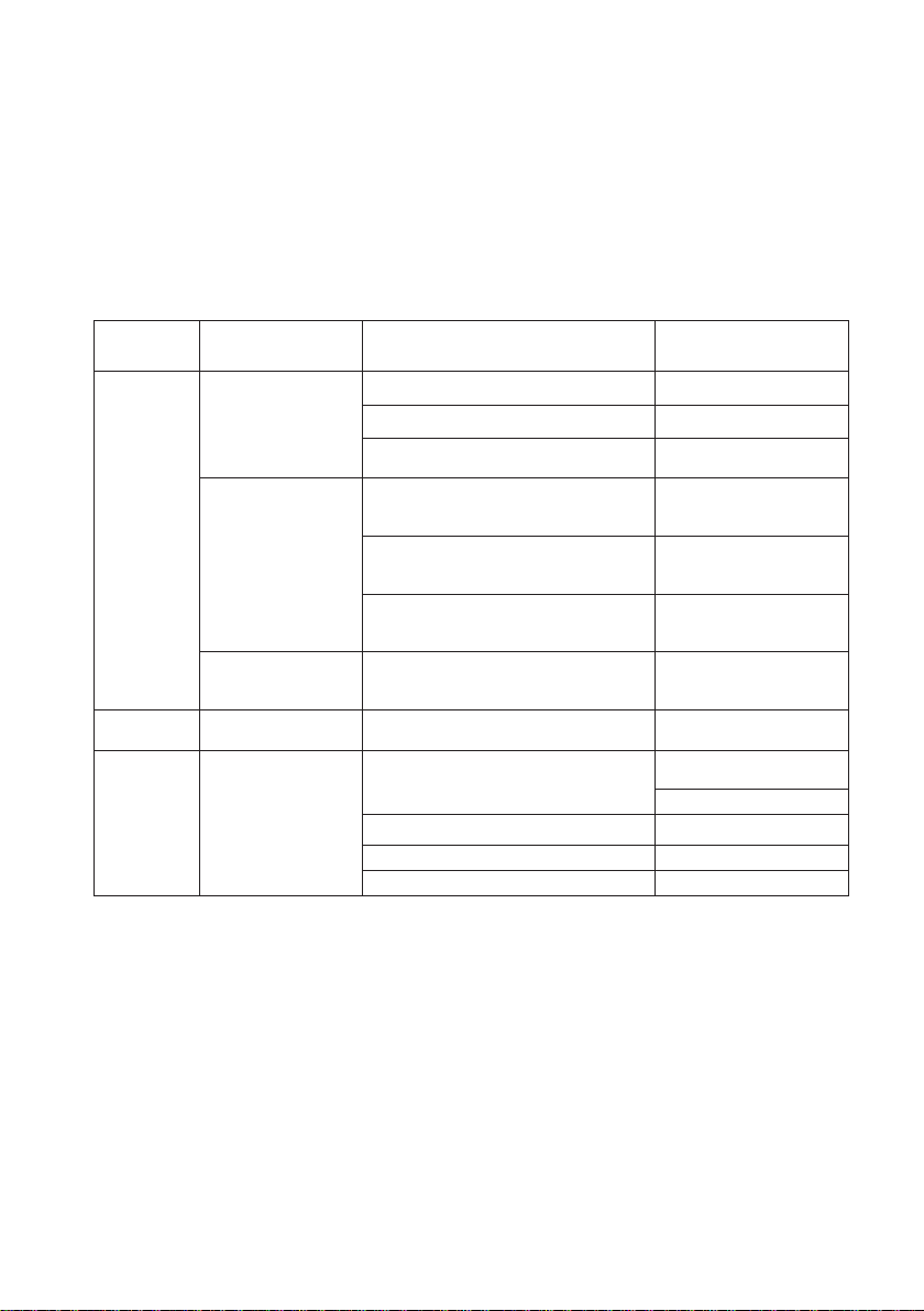
Listed below are the items using settings other than the default configuration (Load
Optimal Default).
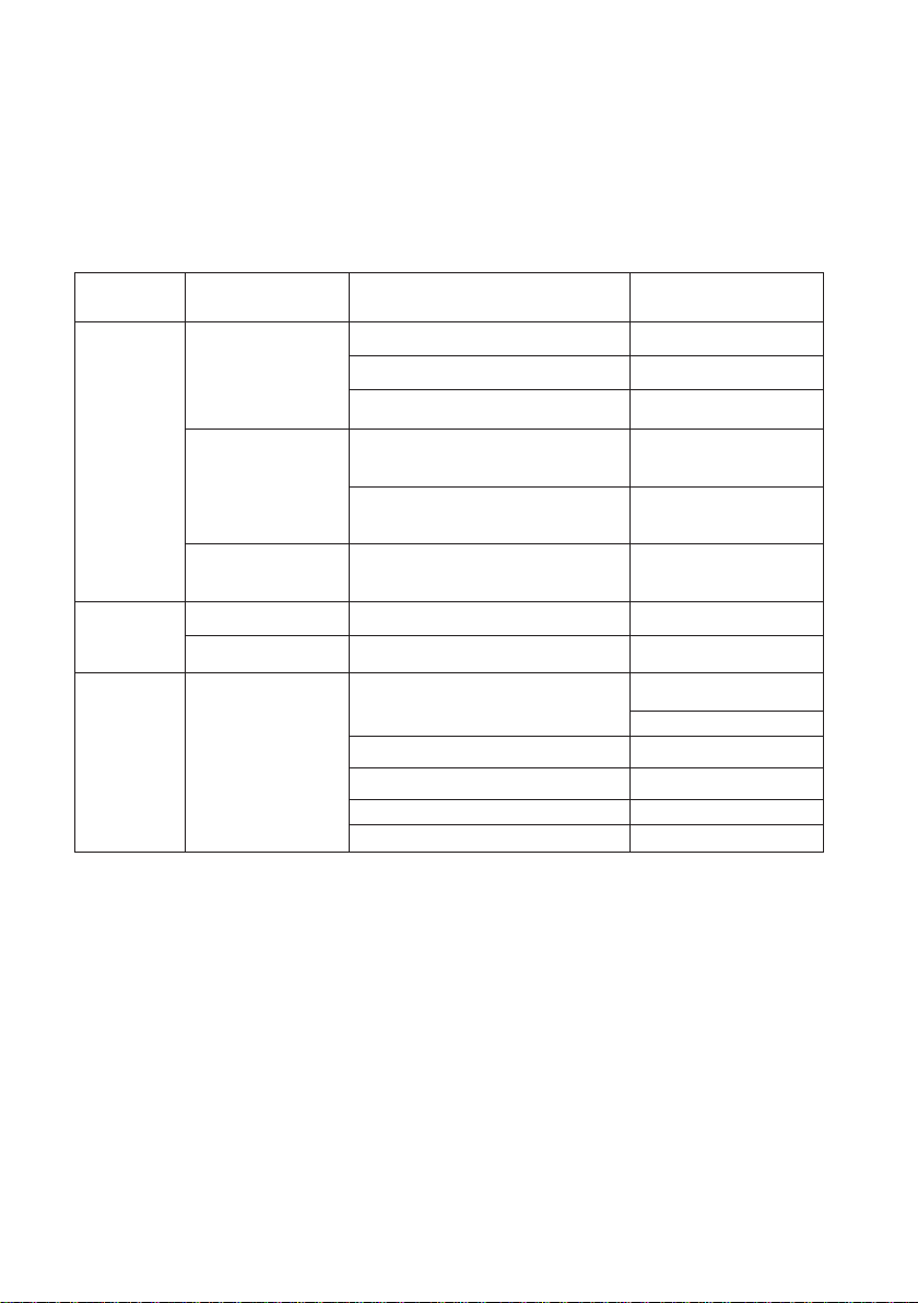
Menu Submenu Item Parameter
Advanced
Peripheral
configuration
Parallel port Disable
Audio Disable
On Board Lan Disable
Video
configuration
DVMT Fixed
IGD DVMT Memory 128Mb
Primary video adaptor Int Graphics IGD
Chipset
configuration HPET Disable
Power Wake on PS/2 Keyboard from S5 Stay Off
Boot
Boot device priority Cd-Rom Drive
Hard Disk Drive
Boot to removable device Disable
Boot to Network Disable
Usb Boot Disable
Save data to Custom Default as well.
8 Technical service manual GEO 10
SK INTEL DG41RQ BIOS CONFIGURATION
The configuration outlined here refers to BIOS version RQG4110H.8
6A.0011.2009.0626.1639
Listed below are the items using settings other than the default configuration (Load
Optimal Default).
Menu Submenu Item Parameter
Advanced
Peripheral
configuration
Parallel port Disable
Audio Disable
On Board Lan Disable
Video
configuration
IGD DVMT Memory 128Mb
Primary video adaptor Int Graphics IGD
Chipset
configuration HPET Disable
Power
ACPI Suspend State S1 State
Processor power managment Disable
Boot
Boot device priority Cd-Rom Drive
Hard Disk Drive
Boot to removable device Disable
Boot to Network Disable
Usb Boot Disable
Boot USB device first Disable

Technical service manual GEO 10 9
WHEEL ALIGNER SOFTWARE
The wheel aligner is supplied with the operating system and software already installed.
The CD-ROM supplied carries a copy of the wheel aligner software.
The DVD-ROM supplied carries a Ghost image of the operating system only, customised for
the motherboard.
The computer is pre-configured to perform the login automatically, so that the user is not
required to identify himself whenever he powers up the wheel aligner computer. The fol-
lowing parameters have been set:
User name: Administrator
Password: administrator [ in lowercase letters ].
During installation or upgrade of the wheel aligner software, the computer is
restarted once or more. When the computer is restarted, you will be prompted
to enter the password: type administrator
The standard user has also been entered to maintain compatibility with a number of vehicle
manufacturers:
standard user:
User name: User
Password: user
NOTE: the wheel aligner must be set for access by means of the Administrator user
name.
When the machine is switched on, the release of the software installed will appear on the
screen.
Compare this release with that stated on the installation CD-ROM supplied
with the aligner.
If the CD-ROM release is more recent than the release installed, upgrade the aligner softwa-
re.
The first time the equipment is switched on, you may be prompted to type the number of
the release of the databank on the CD-ROM supplied with the wheel aligner. In this case,
copy the databank release number (screen-printed on the wheel aligner CD-ROM) into the
data input screen which appears on the display. Follow the instructions on the screen.
NOTE: To restore the original operating system configuration, use the GHOST-
DVD supplied.
WARNING: Before using the GHOST-DVD, check that the screen printing on the
DVD carries the same model as the motherboard to be reset.
WARNING: using the GHOST-DVD causes loss of all the data relating to the jobs
done and the set-ups of the peripherals installed (e.g. the printer).
10 Technical service manual GEO 10
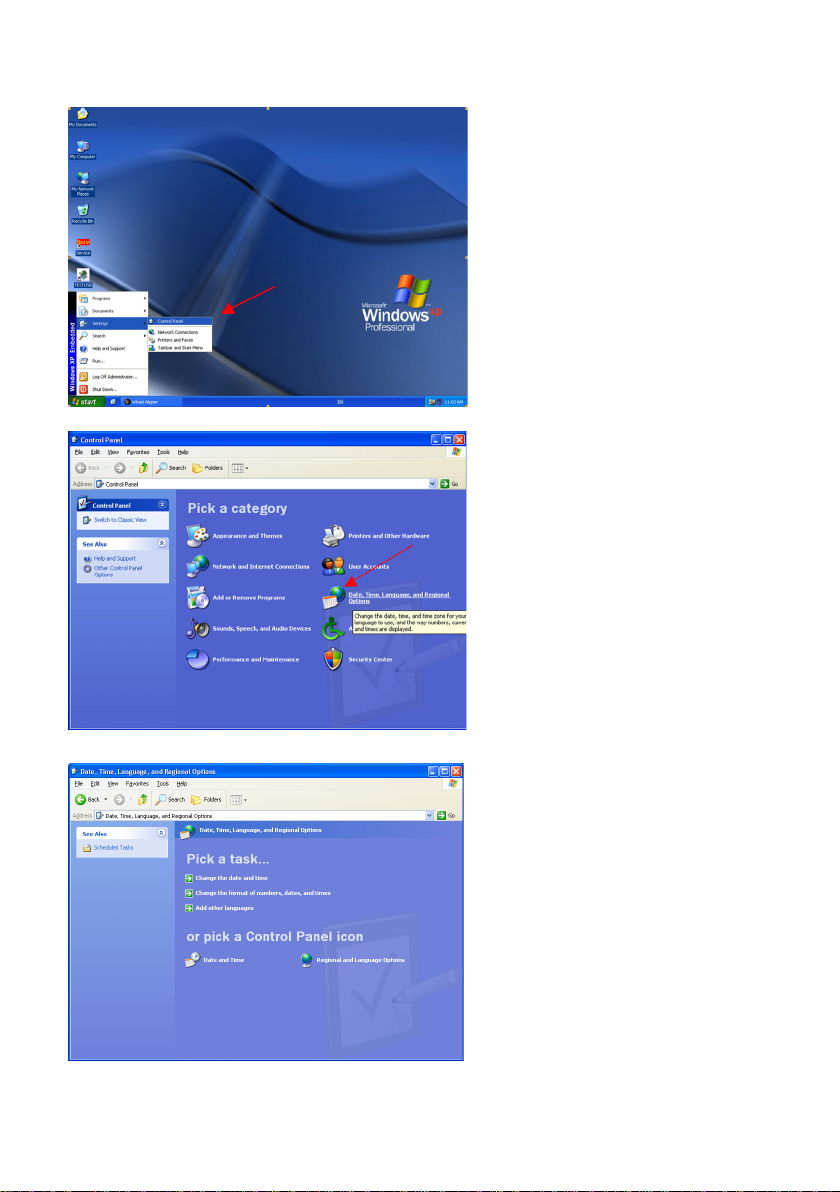
Instructions for changing the language settings
1) Open the Control Panel
2) Open “Date, Time, Language
and Regional Options”
3) Select “Regional and Language
Options”
Otros manuales para GEO 10
1
Tabla de contenidos
Otros manuales de Equilibradora de ruedas de Cormach

Cormach
Cormach TOUCH MEC 1000 SONAR Instrucciones de instalación

Cormach
Cormach MEC 5 Instrucciones de instalación

Cormach
Cormach TOUCH MEC 100 Manual de usuario

Cormach
Cormach MEC 1 Instrucciones de instalación

Cormach
Cormach MEC 200 TRUCK Manual de usuario

Cormach
Cormach GEO 15 Manual de usuario

Cormach
Cormach MEC 810VD-VDL-VDBL Manual de usuario

Cormach
Cormach MOTO MEC Manual de usuario

Cormach
Cormach GEO 15 Manual de usuario


