ControlByWeb XW-112 Manual de usuario


XW-112™ Wi-Fi Water Detector Users Manual
XW-112 User Manual Revisions
Revision Description
1.0 Initial release
Page 2 Xytronix Research & Design, Inc.

XW-112™ Wi-Fi Water Detector Users Manual Introduction
Section 1: Introduction
The XW-112 is an easy-to-use wireless device which onitors the presence of liquids using a GRI-2605
liquid detection sensor (included). It is ideal for applications where liquid level or a water leak ust be
onitored and Ethernet wiring is not accessible or practical to install.
The XW-112 is a self-contained device that requires no additional servers or ControlByWeb devices. The
XW-112 can provide real-ti e status to users through web browsers or the CBW Mobile app. In addition,
it offers the ability to onitor the sensor status and send out e ail alerts (which can be converted to text
essage alerts) whenever an alar condition occurs.
A ter inal strip provides connections to the GRI-2605 Liquid Detection Sensor. No other cables,
interfaces, or PC utility progra s are needed. The XW-112 is powered by an external wall transfor er
(5VDC). Two AA batteries can be installed to provide an AC power-fail alar .
Provisioning the module:
Access-Point ode: Two user accessible push-button switches aid in provisioning the odule. Press the
“Access Point” button anyti e to active the access point ode. Then with a PC or s art phone, connect
to and access the XW-112's internal web server (The XW-112 will always be accessible this way,
regardless of the ode to which it was previously set).
Using the web server, configure the access port, na e, and other setup para eters.
WPS: Alternatively, add the XW-112 to an existing network by pressing the “WPS” (Wi-Fi Protected
Setup) button on both the XW-112 and on your access point (i.e., router).
Network Discovery: Using the Android or iOS app, the XW-112 can be used to configure the Wi-Fi
network as well as any cloud or network settings.
ontrolByWeb loud:
The XW-112 can be configured to auto atically connect to ControlByWeb.cloud after being connected to
a wireless network with internet access. This feature allows internet access to an XW-112 which is
installed behind a network router, without the need to setup port forwarding in the router. This also allows
for easy installation using DHCP without the need to assign a specific IP address to the XW-112.
Since the connection fro the XW-112 is outgoing rather than inco ing, the local router on the network
(where the XW-112 resides) does not need to be configured to forward sockets. This si plifies the
installation since the router configuration is not odified.
Xytronix Research & Design, Inc. Page 3

Introduction XW-112™ Wi-Fi Water Detector Users Manual
1.1.1 Features
➢Wireless Wi-Fi 802.11 b/g/n
➢Direct connections to a GRI-2605 liquid detection sensor
➢Built-in web server for configuration and re ote onitoring
➢Powered fro a 5-Volt DC power adapter
➢Two “AA” batteries provide backup power to send a power-fail alar
➢Alar can control relays on other ControlByWeb devices
➢Send e ail alar s and weekly status alerts (up to 3 addresses)
➢Send encrypted e ails
➢Si ple and easy to use
➢Includes auxiliary protocols: XML and Re ote Services
➢Static or DHCP IP address configuration
➢5-year warranty
1.1.2 Part Numbers and Accessories
Device Description Part Number
XW-112 Wi-Fi Digital Input Monitor with built-in web server XW-112-5
Power Supply Wall Transfor er, 120VAC in, 5V-1A out (included) PS5VW1.0-2.5
Water Leak Sensor Water leak sensor (included). GRI-2605
omplete Kit XW-112, power supply and sensor XW-112-5+PS5V-2605
1.1.3 Water Leak Sensor
The GRI 2605 sensor can detect the presence of water and provides a relay output for control of an
external device. The sensor has two exposed stainless steel electrodes which detect the presence of
water. Although the sensor housing is sealed and is water resistant it is not rated for long-ter
sub ersion by the anufacturer. The sensor operates on 5-Volts DC and functions as a Nor ally
Closed switch. The Red and Black wires power the sensor, the White and Green wires are the relay
output connections.
1.1.4 Wireless ommunication Notes
Due to the nature of wireless co unications, data trans ission and/or reception cannot be
guaranteed. Data ay be delayed, have errors, or be lost. Although delays or losses of data are rare
with a well constructed network, data can be lost due to interference, noise, reflections, or other
environ ental conditions. The XW-112 should not be used in situations where failure to trans it or
receive data could result in da age to property, equip ent, direct, indirect, consequential, or incidental
da age, including da age for loss of business profit, business interruption, loss of data, life, and the
like.
Page 4 Xytronix Research & Design, Inc.
XW-112™ Wi-Fi Water Detector Users Manual Installation and Setup
Section 2: Installation and Setup
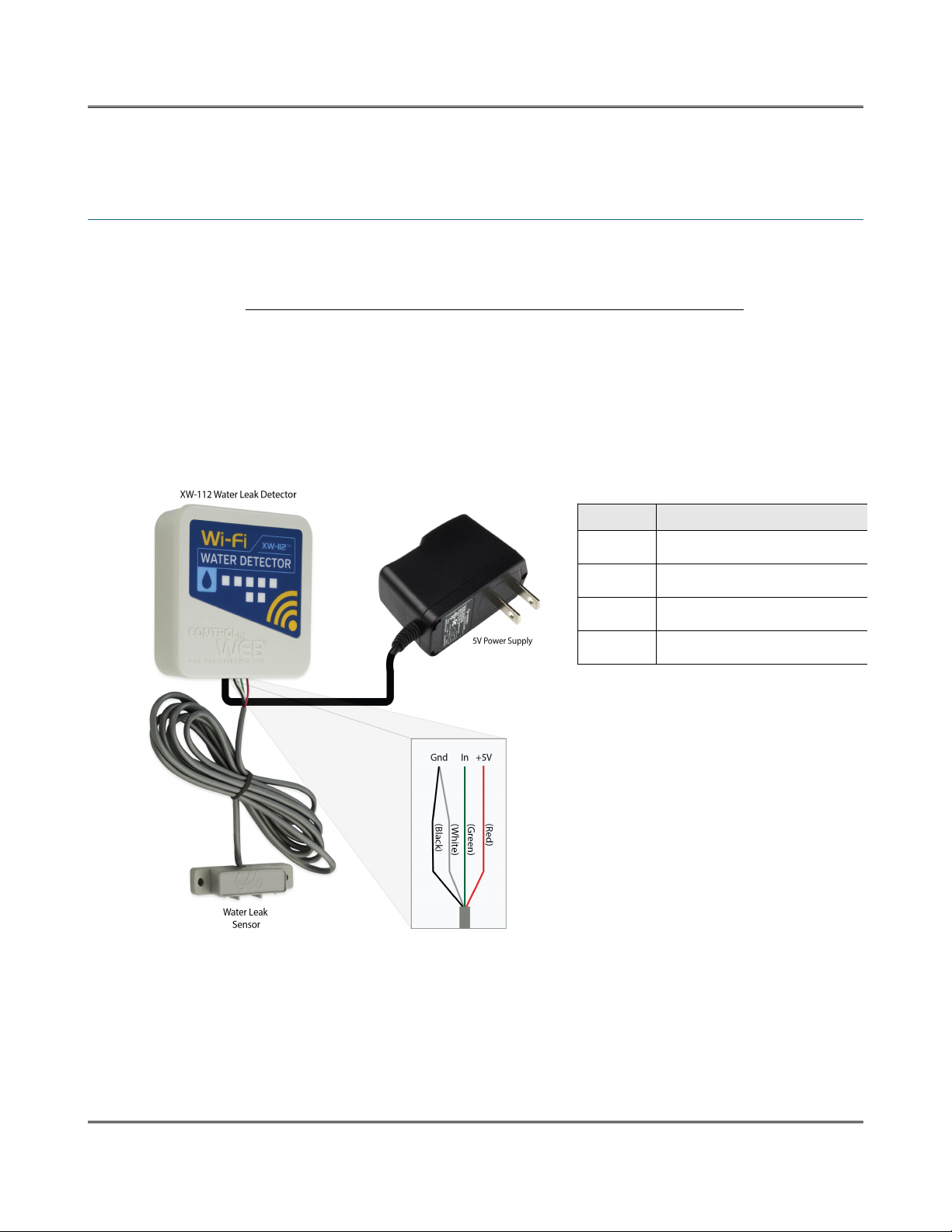
2.1 Power and Sensor onnections
The XW-112 has a 3-position ter inal strip for aking connections to the GRI-2605 Liquid Detection
Sensor. The sensor detects the presence of water or other conductive, non-fla able liquids. The
sensor has 4-wires which are connected as shown below. The XW-112 input works with si ple switch or
relay sensors. Do not connect the 5V output or the digital input to a power source. The input will
work with cable lengths up to 20-feet and should not be routed near otors or AC wiring.
The GRI-2605 has an internal relay. Its contacts (green & white wires) are closed when the sensor is dry.
When the sensor is dry, the digital input will be “On.” When water is detected, the relay contacts open
and the digital input will be “Off.” With the connections shown, the water sensor is a supervised closed-
loop alar circuit such that if a wire is disconnected or the sensor fails, an alar will be generated. The
XW-112 can be progra ed to activate a relay at a re ote location and/or send an e ail warning when
a water leak is detected. After installation, test the sensor with a da p sponge or wet towel and inspect
annually.
Xytronix Research & Design, Inc. Page 5
Wire Description
Red +5V DC
Black Ground
Green Relay contact (closed if dry)
White Relay contact (closed if dry)

Installation and Setup XW-112™ Wi-Fi Water Detector Users Manual
The enclosure can be ounted to a wall or panel with screws (not included). The two screw holes are
located underneath the batteries.
The following installation exa ple shows the water sensor installed on the floor underneath a sink.
2.2 Power / Batteries
The GRI-2605 water sensor has an internal relay which provides a supervised closed-loop alar circuit.
The circuit requires power fro a 5-volt DC wall transfor er and will not operate fro batteries alone.
Installing batteries however, allows the XW-112 to sent a “power
fail” e ail notification if the AC power fails. The liquid detection
sensor is inactive during a power failure. (Note: Your Wi-Fi access
point must be powered by an uninterruptible power supply (UPS) in
order to send a power-failure notification.)
Install the batteries as shown. Observe the “+” and “-” arkings
olded in the enclosure underneath the batteries. Both batteries
should be replaced at the sa e ti e.
Page 6 Xytronix Research & Design, Inc.
Battery Installation

XW-112™ Wi-Fi Water Detector Users Manual Installation and Setup
2.3 Provisioning
After aking the sensor connections and providing power, you ust provision the XW-112 to use it on
your wireless network. The goal is to configure the XW-112 such that it can recognize and attach to your
Wi-Fi access point. There are two ethods for doing this:
1. Access Point
By default, the XW-112 co es up as a wireless access point when powered for the first ti e. Pressing
the "access point" button any ti e also activates the access point ode. It isn't really an access point
because it will not provide internet connectivity to your co puter or s art phone, but it will appear as an
access point, eaning that your co puter or s art phone will detect it as an access point and display it
as such. When acting as an access point, the XW-112 broadcasts an SSID of “XW112-XXXXXX” where
XXXXXX are the last six digits of its MAC address.
With your wireless device (laptop co puter or s art phone) scan for, and connect to the XW112
wireless network. Next, using a web browser, access the XW-112's setup pages, by entering the
following URL in the address bar of your web browser:
http://192.168.1.2/setup.html
After the page is requested, a password pro pt will appear. Enter the userna e and password. The
userna e is admin and the password is webrelay (password is case sensitive). The next chapter
explains each of the setup tabs and screens. Use the WiFi Networks tab for aking the proper settings
to allow the XW-112 to connect to your access point.
Notes About Access Point Mode:
•As an “access point,” the XW-112 functions independently of other wireless networks. It
broadcasts beacons and services Wi-Fi packet requests. In this ode, your co puter or s art-
phone is "connected" directly with the XW-112 on a private network and is NOT using another
Wi-Fi network. Typically you would use this for configuration and not for nor al operation.
•The XW-112 has no hardware “restore defaults” button, to prevent the installer fro being locked
out, the default userna e (admin) and password(webrelay) always work in the access point
ode, even if the password is changed. If the password has changed via the Password tab, both
the new password and the webrelay password will work.
•Only one client (co puter or s art-phone) can be connected to the XW-112 at a ti e.
•SSID and password cannot be custo ized (once again this ode is intended for configuration
only).
•Access point is unsecured and open.
Xytronix Research & Design, Inc. Page 7

Installation and Setup XW-112™ Wi-Fi Water Detector Users Manual
2. WPS (Wi-Fi Protected Setup)
The WPS ethod, provides a si ple ethod for attaching the XW-112 to a wireless network without
needing to use any setup pages. Although using this ethod to connect the XW-112 to the network is
si ple, you will not be able to access the XW-112 web server unless you know the IP address that was
assigned by the DHCP sever (router) or unless DNS services are available on your device. For this
reason, it is reco ended that you use this ethod of configuration only when the XW-112 units have
been pre-configured to operate in a non-web-server ode or when you have full access to the DHCP
server so you can obtain the IP address that was assigned.
To begin, press the WPS button on your wireless router or access-point. You will generally have about
two inutes to connect wireless devices to the network with WPS. Now re ove the cover of the XW-112
and press the “WPS” push button. After a few seconds, the XW-112 should register itself with the router
or access-point. If WPS fails, the XW-112 will auto atically enter the access point ode.
The XW-112 will use DHCP to obtain an IP address after a successful WPS association. Additionally, the
connection infor ation is also broadcast using DNS. If you need to access the XW-112 using its
internal web server you will need to obtain the IP address that was assigned to the XW-112 through your
DHCP server or router. Alternatively, if using an DNS capable device, it ay be accessed by entering
the appropriate URL into the address bar of your web browser:
http://xw-112.local/setup.html
Page 8 Xytronix Research & Design, Inc.

XW-112™ Wi-Fi Water Detector Users Manual Installation and Setup
2.4 Application Example
Remote Alarm Example
You wish to receive an e ail alert and activate a buzzer or light to indicate that a water leak has
occurred. The sensor is within range of a Wi-Fi access point and AC power is available.
Install a WebRelay™ or WebSwitch™ in your office and connect it to your Ethernet network. Connect a
buzzer or light to the relay contact. The WebRelay ust be accessible fro the Wi-Fi network and be
assigned a static IP address. Your Wi-Fi network ust have adequate coverage to connect to the XW-
112 as well. Connect the GRI-2605 sensor to the XW-112 and ount it near the floor where the water is
to be detected. To provide for an AC power-fail e ail alar , install two AA batteries. (Note: Your Wi-Fi
access point must be powered by an uninterruptible power supply (UPS) in order to send a power-failure
notification.)
First, the XW-112 ust be configured to access your Wi-Fi network. If no network profiles have been
configured, the XW-112 will auto atically enter access point ode and you can access the XW-112
directly with a co puter or obile device with a wireless connection. If the XW-112 has been previously
configured for other uses, press the Access Point button. Scan for, and attach to the XW112-XXXXXX
wireless network. Access the setup pages with the following URL: http://192.168.1.2/setup.ht l
Configure the XW-112 to connect to your wireless network. Navigate to the WiFi Networks tab and fill in
the appropriate settings for your Wi-Fi network. Obtain an available IP address fro your network
ad inistrator. Press the Sub it button at the botto of the page. (The XW-112's internal web server is
always enabled and accessible.)
Navigate to the Water Sensor tab. On the mail Alerts setting, select On. Change the Description text to
a descriptive na e such as “Laundry Room Water Sensor.” This text ay be up to 40 characters long
and appears on the Control Page and in e ail essages when e ail alerts are enabled. Click the
Sub it button at the botto of the page.
Navigate to the mail tab and enter the SMTP server settings as well as the userna e and password (if
required). You ay need to contact your e ail provider for the exact settings to use. To provide ongoing
assurance the XW-112 is working, enable the Weekly Status mail option.
Set the Remote Relay Options to Remote Command Opposite of Sensor. With this setting the re ote
WebRelay or WebSwitch's relay will be On when the water sensor detects water, and Off when the
sensor is dry. This setting is needed since the water sensor is a supervised closed-loop alar circuit.
Upon selecting an action, the re ote relay options will show, and ask you to specify the WeRelay or
WebSwitch's IP address, port, relay nu ber, etc. Enter these settings for the WebRelay/WebSwitch and
press the Sub it button at the botto of the page.
Once all the appropriate settings have been applied, click on the Reboot button on the Main tab, the
XW-112 will then reboot and begin operation. The XW-112 will no longer broadcast an SSID. The web
page will now be available at the assigned IP address. If a water alar is detected, an e ail will be sent
and the re ote relay will be activated. You will receive a weekly e ail which indicates the XW-112 is
connected and working (if selected in the E ail tab).
Xytronix Research & Design, Inc. Page 9
Web Server XW-112™ Wi-Fi Water Detector Users Manual
Section 3: Web Server
The internal web server presents two classes of web pages: Setup pages and Control pages. Setup
pages are used by an installer to provision and configure the XW-112. The Control page displays water
sensor and battery status infor ation. The Control Page displays easure ent and status infor ation
for the user.
To access the setup pages, enter the following URL in the address bar of your web browser:
http://192.168.1.2/setup.html
To access the control page, enter the following URL in the address bar of your web browser:
http://192.168.1.2
The internal web server is always enabled and it can be accessed any ti e.
Note that if you are accessing the unit as an access point, the above IP address will work even if you
have previously changed the IP address or port in the setup pages. If you are accessing the unit through
the network after it has been configured, you will enter the IP address that was assigned to the device.
If the XW-112 has been added to a network using WPS, it will use DHCP and you will need to use the IP
address assigned to it by the DHCP server or router. This can be found by logging into the DHCP
server/router, or by using DNS. In a web browser, enter the DNS na e: http://xw-112.local/
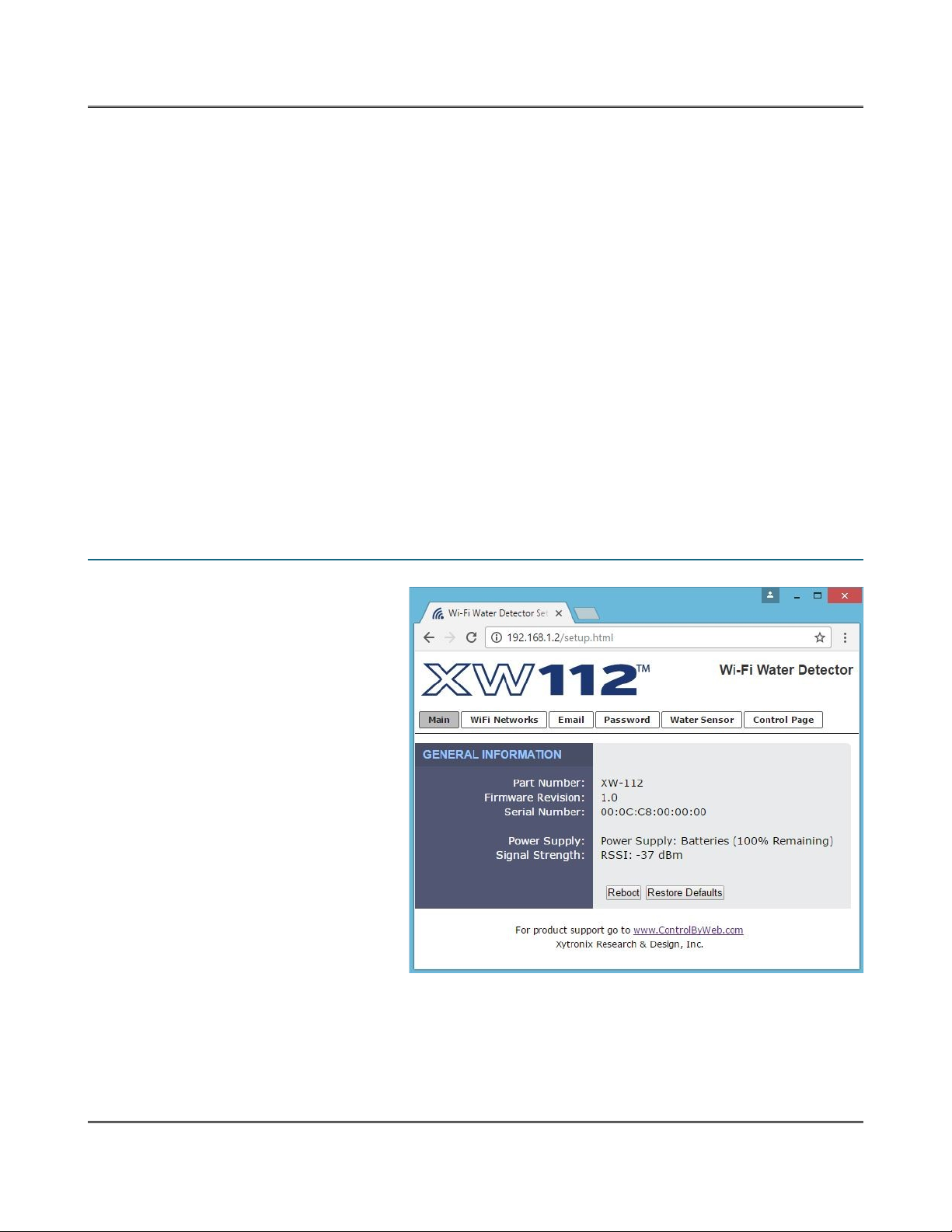
3.1 Main Tab
This is the initial page that is
displayed when accessing the setup
pages. It displays odel and serial
nu ber infor ation, and has
navigation tabs which allow access to
the configuration and setup settings.
Page 1 Xytronix Research & Design, Inc.
Este manual sirve para los siguientes modelos
1
Tabla de contenidos


