
Condux Fiber Optic Cable Puller Trailer Manual de instrucciones

Fiber Optic Cable Puller Trailer
USER'S GUIDE & SAFETY MANUAL USER'S GUIDE & SAFETY MANUAL
2
Important Safety Notice
Read and understand these usage and safety instructions before using a Condux Fiber Optic Cable
Puller Trailer. Observe all safety information on this page and note specific safety requirements as
explained by procedures called out in this manual. Failure to follow these instructions could result in
serious personal injury or death. Save this user’s guide for future reference.
®
If you have questions on:
SAFETY - OPERATIONS - APPLICATIONS
CALL 1-800-533-2077
CONDUX
ADVERTENCIA:
Favor de leer y comprender todas las instrucciones de operación y seguridad antes de usar la máquina.
Si Ud. no comprende las instrucciones favor de consultarle a su jefe.
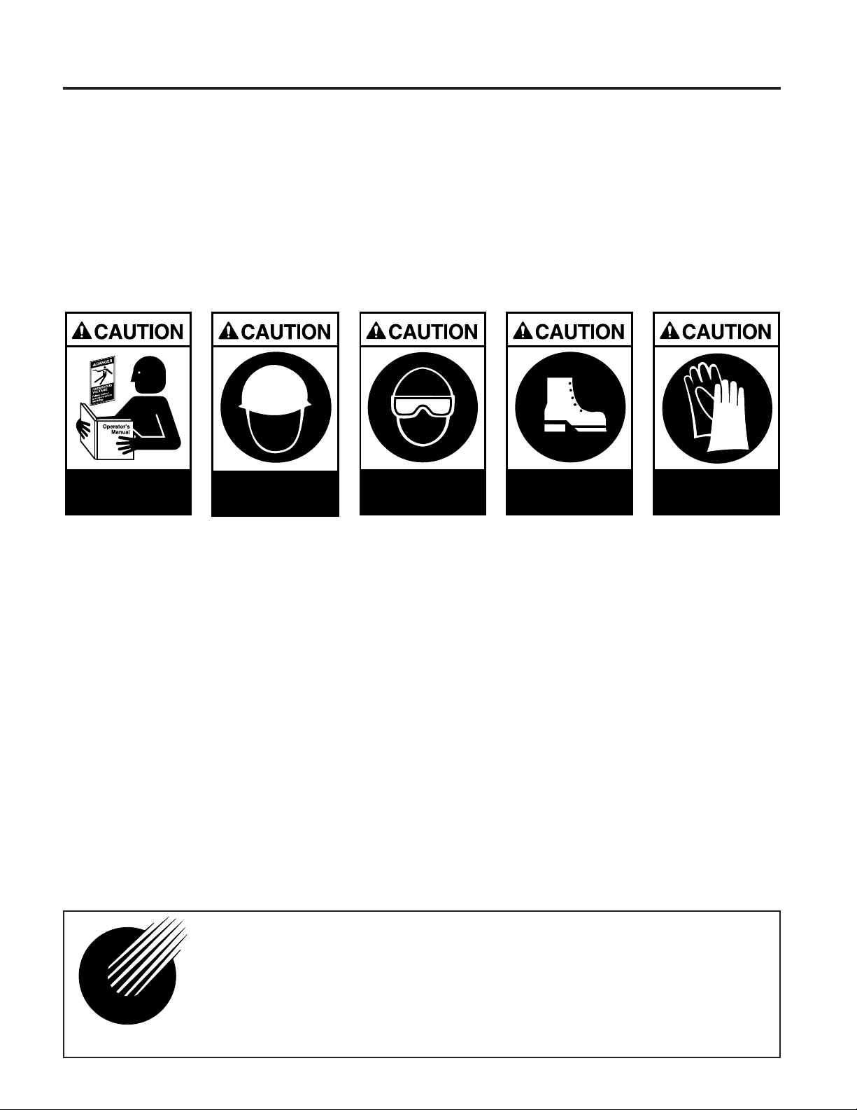
READ MANUAL
FIRST
WEAR
HARD HAT
WEAR SAFETY
GLASSES
WEAR SAFETY
SHOES
WEAR SAFETY
GLOVES

General Information
Fiber Optic Cable Puller Trailer .....................................4
Product Specifications
General Dimensions .............................................4
Power Supply Specifications .......................................4
Hydraulic Specifications ..........................................5
Other Specifications .............................................5
Safe Operating Practices
Work Area Safety ...............................................5
Hydraulic Systems ...............................................5
Electrical Components ...........................................6
Jobsite Floor Plan
Jobsite Floor Plan Illustration ......................................6
Set Up The Trailer
Stabilizing & Leveling the Trailer.....................................7
Set up the Cable Puller
Cable Pulling from Trailer .........................................9
Cable Pulling with the Remote Mounting Stand . . . . . . . . . . . . . . . . . . . . . . . .9
Unpack the Components .........................................10
Connect the Hydraulics ..........................................10
Set up the Electronic Control System
Switch Configuration ............................................12
Connect the Electronics .........................................12
Setting up the Electronic Control Box ...............................14
Digital Chart Recorder Set up .....................................15
Data Download Instructions .......................................16
Operating the Power Unit
Fuel & Fuel Tank ...............................................16
Final Inspection ................................................17
Start the Power Unit ............................................17
When the Cable Pull is Complete
Stop the Power Unit ............................................18
Remove Pressure from Hydraulic System ...........................18
Remove Hydraulic Hoses ........................................18
Disconnect the Electronics .......................................19
Additional Takedown Procedures
Remove Capstan from the Puller ...................................19
Return Puller to Travel Position ....................................19
Load Foot Control Unit ...........................................20
Prepare Unit for Transport ........................................20
Appendices
A. Trailer Towing Safety Instructions ................................20
B. Routine Maintenance .........................................21
C. Replacement Parts ...........................................21
Table of Contents
1.
2.
3.
4.
5.
6.
7.
8.
9.
10.
11.

4
Congratulations on your purchase of the Condux Fiber Optic Cable Puller Trailer.
This unit is designed to provide a safe and efficient means to transport and
operate the Condux Fiber Optic Cable Puller (figure 1). The trailer offers the
platform for a self-contained cable pulling system including a hydraulic power
source, cable puller mounts, leveling and stabilizing hardware, and a lockable
storage area (figure 2).
This User Guide and Safety Manual will help you become more acquainted with
the features and functions of your Fiber Optic Cable Puller Trailer. As with all
Condux products, it is designed to be used only by trained craftspeople. Be
certain that you understand the operating and safety instructions in this manual
before using the equipment. Keep this manual as a permanent part of your
trailer package.
Product Specifications
A. GENERAL DIMENSIONS
Weight (wet) not including cable puller: 950 lbs.
Track: 60 inches
Overall width: 80 inches
Tongue weight: 200 lbs.
Tire Size: P205/75R14
Rim Size: 14" x 6"
Coupling Size: 3" lunette Eye
Overall Height: 51 inches
Lighting adapter: 7 pin connector
B. POWER SUPPLY SPECIFICATIONS
GAS-Briggs & Stratton V-Twin Vanguard OHV 16 h.p. gasoline engine,
electric start
Fuel requirements: unleaded fuel only, 85 minimum octane, 10% or less
ethanol blend
Fuel capacity: 5 gallons
1.
2.
Figure 1 Figure 2
General Information

5
C. HYDRAULIC SPECIFICATIONS
Capacity: 8 gpm @ 2000 psi
Reservoir capacity: 5 gallons
Filtration: 10 micron nominal
Oil Requirements: Petroleum based hydraulic oil with antiwear properties and
high viscosities over 140
Relief Valve Setting: 2150 psi
D. OTHER SPECIFICATIONS
Electronics power requirements: 12 VDC
Pulling Capacity: 1000 lbs with 30" dia. Condux capstan
Towing Requirements: Class I hitch, 200 lbs. tongue weight, 2000 gross trailer
weight
Safe Operating Practices
Your Fiber Optic Cable Puller Trailer, as with all Condux products, is designed for
safe operation; however, general jobsite safety practices must be followed. In
addition, specific safety messages are printed throughout this manual and also
appear on safety labels on the product.
A. WORK AREA SAFETY
1. Read and understand all operating instructions and safety messages before
operating.
2. Wear protective safety equipment such as: hard hat, safety glasses, safety
shoes, work gloves.
3. The safe operation of this equipment requires that the operator(s) be on
stable footing.
4. Stay clear of cable or lines under tension.
5. Be aware of the location of all underground utilities in your work area.
6. No smoking or open flame in the work area. An explosion hazard exists as
the trailer houses a gasoline tank.
B. HYDRAULIC SYSTEMS
Escaping fluids under pressure can penetrate the skin and cause serious personal
injury. Observe the following precautions to avoid hydraulic hazards:
1. Tighten all connections before applying pressure. Relieve pressure before
disconnecting hoses.
2. Check for leaks with a piece of cardboard. Do not use hands!
3. Do not exceed working pressure of hydraulic hoses.
4. Visually inspect hoses regularly and replace if damaged.
3.

6
C. ELECTRICAL COMPONENTS
The Electronic Control Box is an electrical device. Electric shock hazard exists
that could result in severe personal injury or death. Observe the following
precautions to avoid electrical hazards:
1. Do not operate in or near water. This includes setting the Electronic
Control Box on a wet surface or exposing it to rain.
2. Do not remove cover of Electronic Control Box. No user-serviceable parts
inside. Refer servicing to qualified service personnel.
3. The Electronic Control Box power switch should be in the off position before
connecting or disconnecting any cords.
Jobsite Floor Plan
A few minutes spent planning your equipment’s placement (layout) at the jobsite
will benefit both the operation of the equipment and the safety of your personnel at
the site. It is best to determine the layout of equipment before stabilizing and
leveling the trailer (section 5A). Condux recognizes that no two jobsites are the
same, but recommends a few general guidelines to get the most benefit and safest
operation from your Fiber Optic Cable Puller Trailer.
A. POSITION THE CABLE PULLER
Ultimately, the cable will be pulled from its exit point parallel to the capstan
(figure 4). Several options are available on the Condux trailer to achieve this. The
cable puller can be located in one of three mounts and rotated perpendicular or
parallel in each. Review these options using the accompanying diagrams and
determine where to position the trailer (figure 3).
B. REMOTE MOUNTING STAND
If no suitable puller position can be achieved on the trailer, a remote mounting
stand (supplied) may be used, see section 6B.
4.
LEFT SIDE CENTER
RIGHT SIDE
Figure 3

7
C. POSITION THE TRAILER
Position the trailer (in the position determined in 4A) with the tow vehicle. It is not
recommended that any other means be used to move the trailer.
Set Up The Trailer
It is essential that the trailer set-up instructions are followed in order that they
appear in this user guide and safety manual. Using the following procedures
will allow the trailer to be set up in a short period of time and yield optimum
performance.
A. STABILIZING AND LEVELING THE TRAILER
1. Use only the adjustable jacks (3 supplied, replacement jack part number
02290764) for trailer stabilizing and leveling. Jacks must be placed securely
only on jack mounts located on the trailer frame (figure 5). Do not attempt
to locate jacks in any other position! To secure a jack in position, align jack
with jack mount and insert safety pin. Raise and lower jacks by simply
rotating crank handle.
!WARNING: Chock wheels and level trailer before setting up
cable puller and other pulling equipment. Use wheel chocks and
all three leveling jacks as described in the procedure below.
Failure to properly level trailer may result in the trailers unexpected
movement causing severe personal injury and equipment damage.
20°
ECB
OPERATOR
FOOT CONTROL
HAZARD AREA
Figure 4
5.

8
2. Begin to stabilize the trailer by placing a wheel chock (2 supplied) behind
each trailer wheel (figure 6).
!WARNING: Load must be distributed evenly before unhitching
trailer. Failure to do so may cause the trailer tongue to flip upward
causing severe personal injury.
3. Remove trailer from tow vehicle. The trailer should be in position for cable
pulling at this time (section 4). Use an adjustable jack on the front frame
jack mount to lift the trailer from the tow vehicle (figure 7). Place jack in
jack mount as described in section 5A-1 and then disconnect ball hitch or
other hitch mechanism. Then lift trailer from tow vehicle by using the crank.
Raise no more than necessary to clear tow vehicle.
4. One jack will remain on the tongue of the trailer. Place the last two jacks at
the rear corners of the trailer. Placement of rear jacks is critical to avoid
getting in the way of the pulling equipment. Note that there are two jack
mounts provided at each rear corner (figure 8).
5. Level the trailer by using the crank handles on the jacks. Raise and lower
each jack to provide a level surface for the cable pulling equipment.
Figure 7 Figure 8
Figure 5 Figure 6

9
Set Up The Cable Puller
A. FOR CABLE PULLING FROM TRAILER
Move the cable puller from the travel position, if necessary, to achieve the best
possible pulling position as determined in section 4. There are two steps to
achieve this.
1. Change the placement of the cable puller on the trailer bed by inserting the
puller into one of the two mounting holes on the side rails of the trailer
frame. Note that the center (travel) position on the trailer bed already has
its own mount. Pin the mount from below the trailer bed. Lower the cable
puller on the mount.
!CAUTION: The cable puller is heavy (125 lbs.). Lift only with
proper equipment or sufficient man power. Personal injury may
result if improper lifting practices are used.
2. Adjust the cable puller on the mount, corner positions only (figure 9). Align
holes in mount and cable puller. Place the lock pin (supplied) through the
entire mount and hook to secure the cable puller.
B. FOR CABLE PULLING WITH THE REMOTE MOUNTING STAND
In the event that the trailer cannot be positioned for optimum cable pulling
operation, you may choose to use the remote mounting stand integrated on the
trailer bed.
1. Remove the cable puller from the remote mounting stand first. Do not
attempt to remove the remote mounting stand from the trailer bed with the
cable puller attached.
2. Use a 1 1/8" wrench to remove the bolts securing the remote mounting
stand to the trailer bed (figure 11).
3. Position the remote mounting stand on a level surface for cable pulling.
Follow the guidelines in section 4.
4. Loosen the two screw-knobs on the base and slide the support tubes until
centered. Retighten the two screw-knobs.
6.
Figure 9 Figure 10

10
5. Mount the cable puller on the remote mounting stand. Be sure the capstan
is placed between the support tubes, not over the support tubes (figure 12).
C. UNPACK THE COMPONENTS
1. Remove the capstan from its storage rack and place on the cable puller.
Align slots on capstan with pins on shaft and push on (figure 10). The
capstan sleeve contains a spring that must be compressed all the way,
then rotate clockwise until the capstan springs into place over the shaft
pins. The pins on the shaft must be visible through the holes in the capstan
sleeve. You should not be able to rotate the capstan at this point if it is
properly installed.
2. Remove the foot control and hydraulic hoses from the trailer bed. Set aside
for connection later.
3. Remove the Electronic Control Box, if equipped, and its power cord
(supplied). Set aside for connection later.
D. CONNECT THE HYDRAULICS
!WARNING: Escaping fluids under pressure can penetrate the
skin and cause serious personal injury. Observe the following
precautions to avoid hydraulic hazards:
1. Tighten all connections before applying pressure. Relieve
pressure before disconnecting hoses.
2. Check for leaks with a piece of cardboard. Do not use hands!
3. Do not exceed working pressure of hydraulic hoses.
4. Visually inspect hoses regularly and replace if damaged.
Figure 11 Figure 12
Tabla de contenidos
Otros manuales de Equipos industriales de Condux

Condux
Condux 08097100 Manual de instrucciones

Condux
Condux TESMEC PE1250 Manual de usuario

Condux
Condux TESMEC URW24 Manual de usuario

Condux
Condux 819 D.Drill Swivels Manual de usuario

Condux
Condux TESMEC PT1150 Manual de usuario

Condux
Condux CableGlider Manual de instrucciones

Condux
Condux APS75 Manual de instrucciones

Condux
Condux CableGlider LW Manual de instrucciones


