Component Playgrounds SS31-10 Manual de usuario

Installation Instructions
SS31-10
Required Tools
Wheelbarrow Tape Measure
Shovel Level
Digging Bar or Pick Open End or Box Wrenches: 5/8”, 9/16”, ½”
Allen Wrench (Provided) Ratchet Handle & Sockets: 5/8”, 9/16”, ½”, 17mm
Marker Pen Ladder
PLEASE READ AND UNDERSTAND ALL INSTRUCTIONS BEFORE BEGINNING
*Before digging, Please obey local laws by notifying your local utilities marking
organization*
1. Select an area in your yard that is reasonably level and meets the space requirements for your
equipment. Ground Space: 15’ x 28’. Play Space: 19’ x 39’.
2. Please refer to the Top Rail/Out Rigger assembly sheet and assemble your top rails as instructed.
3. Using the measurements from the top view diagram, measure and mark the position of the swing
hangers and ladders on each of the top rails. Set aside.
4. Place over head ladder onto the ground in the desired location. Measure and adjust as necessary to
allow for the proper play space.
5. With the Horizontal ladder in its proper position in the yard, mark the location for the holes where the
two vertical ladders will stand. Move the horizontal ladder and dig the holes. (See installation
instructions for dimensions and hole sizes for cementing.)
6. Lay each vertical ladder on the ground near the hole where it will eventually stand. Make a mark 15” from
the top of the ladder onto each ladder rail. Move the adjustable sleeves to these marks and position them
to receive the overhead ladder by turning them to point at a 90 degree angle (towards what will become
the inside of the structure) away from the upright ladder. Repeat this process with the 10’ ladder. Make
your marks at 39”. Secure the set screws.
7. Insert the 9’ top rail into the top sleeve of the ladder. Secure the set screws.
8. Place the ladder into its hole. Hint: Be sure that the adjustable sleeves are prepared to receive the
horizontal ladder.
9. Lay the 10’ ladder on the ground with the bottom of the ladder just over the hole where it will
eventually stand.
10. Place the 13’11” outrigger about 12’ away from the hole. Assemble and attach the swing hangers to
the 13’11” outrigger.
11. Position the outrigger upside down on the ground. Assemble the “A” frame legs. (See #2 A frame leg
assembly.) Slide the outrigger into the top sleeve of the vertical ladder.
12. Using two strong adults, stand the structure up and allow the ladder to fall into the hole previously dug.
Check and make sure that the outrigger is still properly positioned inside of the ladder top sleeve. The out
rigger can be adjusted as follows: While securely holding the ladder, take hold of the “A” frame portion
and push or pull as necessary. When you are satisfied that the outrigger is properly positioned inside the
ladder top sleeve, secure the set screws. Note: The unit will not be level at this point.
13. Adjust the “A”frame legs in the play space as desired.
14. Mark the holes for the “A”frame legs. Move the legs out of the way and dig the holes. Hint: Keep
most of the hole to the inside of the leg.


15. Place the legs into the holes.
16. Using two strong adults, lift and slide the horizontal ladder onto the adjustable sleeves at the swings
side of the structure and secure the set screws. (See instructions for overhead ladder to upright
ladder assembly.) Hint: Do not push the overhead ladder tight against the vertical ladders. Leave a
½” - 1” gap between the vertical ladder rails and the overhead ladder. This will allow for easier
adjustment of the overhead ladder in the future.
17. Bring the other vertical ladder up to the horizontal ladder and secure set screws as before.
18. Attach the swing hangers onto the 9’ top rail.
19. Slide 3rd leg sleeve onto the top rail that is sleeved into the outside of the 10’ ladder.
20. Measure 5 ½’ - 6’ away from the 10’ Upright Ladder to mark and dig the hole for the Third Leg (see
#1B hole sizes for cementing).
20. Measure 5 ½’ - 6’ away from the 10’ Upright Ladder to mark and dig the hole for the Third Leg (see
#1B hole sizes for cementing).
21. Before installing the third leg, locate the third leg. Insert ⅜” x 3½” Hex Bolt and loosely thread ⅜”
Nut into the bottom hole. Nut will not thread all the way on and bolt will be loose. (This is to act as
an anchor in the concrete and does not need to be tight.)
22. Install Third Leg by dropping the end into the hole and sleeving the top into the 3rd leg sleeve. Use
the 3/8” x 2 3/4” hex bolt and 3/8” nyloc nut. Then secure 3rd leg with set screw on under side. (see
diagram #4) When properly positioned, secure the set screws in the top of the 3rd leg sleeve.
23. Attach the slide bracket and slide as shown on the slide assembly sheet.
24. Measure the height of the top rail to insure proper swing height.
25. Level the structure.
26. Mix concrete according to the package directions. Pour the concrete. You will use approximately 6-7
80 pound bags in each ladder hole and 1-1/2 bags in each of the other holes. (See installation
instructions #1 Hole sizes for cementing in the set.)
27. Allow the concrete to cure 3 - 5 days before using.
28. Attach the chain and swing seats and enjoy your Component Playground.

Top Rail Assembly
Step 1: Slide the Swing Hangers and tighten onto the Top Rail during the Top Rail
Assembly process. (Refer to spacing diagram and graphic found above)
Step 2: Slide the ends of the 10’ Top Rail as far as it will go into the Sleeve of the
Triple End.
Step 3: Insert and tighten (4) 3/8” x 3/8” set screws into each of the Triple End
Sleeves using Allen Wrench provided.
Step 1
Step 2

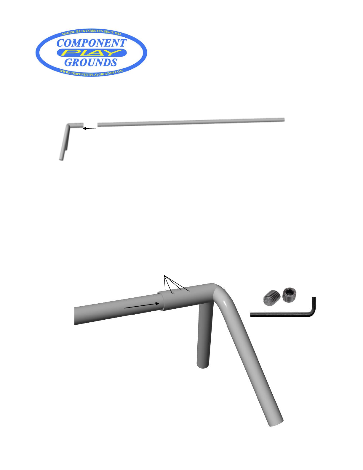
Two piece Top Rail
Assembly
*Make sure to line up the set screws so they make a straight line
as show in the graphic above.
Step 1:
Step 2:
Step 3:

Installation Instructions
Model SS31-10
Ground Space 15’ x 28’
Residential Play Space 19’ x 39’

Top Rail
Set
Screws
Set Screw
20”
28”
24”
Upright
Ladders
Top Rail
Slide Top Rail joint into place
about 1 inch inside the Ladder
Top Sleeve & secure with two
3/8” x 3/8” Set Screws
Upright Ladder
set screw holes
Set
Screws
Set Screw
Hole Sizes for Cementing in the Set
20”
28”
24”
Upright
Ladders
Hole 28” x 20” x 24”
(Approximately 6-7 80 lb. bags
of concrete mix per hole)
Set Screw
Upright Ladder
Set Screws
Set Screw
Adjustable Sleeve
Horizontal Ladder
Top Rail
Triple End
A-Frame
Leg
3/8” x 2 ¾” Hex Bolt with
3/8” Nyloc Nut (1 each per
leg)
3/8” x 3/8” Set
Screw (1 each per
leg)
Slide in leg, bolt in
place and secure
with set screw.
#2 A-Frame Leg Assembly
(B) A-Frame
Legs
Holes 18” x 12”
(Approx. 1 ½, 80 lb.
bags concrete mix
per hole)
12”
18”
(A) Upright
Ladder
20”
28”
24”
(C) 3rd Leg
Hole 18” x 18”
(approx. 2, 80 lb.
bags of concrete mix)
A-Frame Leg attachment
to Triple End
3/8” x 2 ¾” Hex
Bolt with 3/8”
Nyloc Nut (1
each per leg)
3/8” x 3/8” set screw
( 1 each per leg)
Slide in leg, bolt in
place and secure
with set screw
Triple
End
A-frame
leg
SS31-10 Model Continued

Tighten 3/8” x1/2” set screws on the top
sleeve of the ladder (2 set screws)
Slide
½” x 2 ¾” bolt
through the two
holes and secure
with the 3/8”
nyloc jam nut.
Insert 3/8” x 3/8” and
3/8” x ¼” set screw
and tighten to help
secure the 3rd leg in
place.
3rd Leg Sleeve
Nyloc Nut
3rd Leg
Third Leg Sleeve
Tighten 3/8” x 3/8” set screws on
top sleeve of ladder (2 set screws)

Note: We recommend you check the pendulum in the
swing hangers at least every 6 months for normal wear.

RAVE/ROCKET SLIDE MOUNTING INSTRUCTIONS
1. Attach the slide bracket to
the upright ladder by placing
the carriage bolt through the
ladder and through the holes
in the bracket. Then secure
with the flate washer, loc
washer, and hex nut. AS
SHOWN ON RIGHT. (It is
recommended that you level
both the ladder and the
bracket before you tighten
hex nut in place.)
2. Attach the slide to the bracket by
placing the slide in place on bracket.
Then drilling with a 3/8” drill bit
through the holes in the bracket into
the slide. (Holes in the bracket should
line up with mold for holes in the
slide.) Then insert the BHS bolt
through the slide holes and through
the holes in the bracket. Then secure
with the flat washer, loc washer, and
hex nut. AS SHOWN ON RIGHT.
3/8” x 3” Carriage
Bolt
Slide Bracket
3/8” Hex Nut
3/8” Loc Washer
3/8” Flat Washer
3/8” x 1 ¼” BHS Bolts
3/8” Flat Washer
3/8” Loc Washer
3/8” Hex Nut

Tabla de contenidos