Cleanburn Norreskoven Manual de usuario

NØRRESKOVEN
Mk 2
M U L T I F U E L
S T O V E
Installation and Operating Instructions
An accredited competent person must carry out the installation of this appliance;
alternatively, your local Building Control Officer can approve the completed
installation, should a non-accredited engineer undertake the installation. It is an
offence, under UK law, not to comply with this advice. Please hand these
instructions to the stove user when the installation is complete. Leave the system
ready for operation and instruct the user in the correct use of the appliance and
operation of controls.
v01.11b

Nørreskoven
Technical Specification
Stove Mass 100 kg
BS/EN 13240
Total Efficiency 73.5 %
Nominal Heat Output 4.4 kW
Mean CO Emission (at 13% O2) 0.17 %
Mean Flue Gas Temperature 311 °C
Flue Gas Mass Flow 4.6 g/s
This appliance is not suitable for use in a shared flue
This appliance is suitable for intermittent burning

Important! –Read This First
This stove has been designed and assembled so that it may be used to burn wood logs in a Smoke
Control Area.
Find out if you are in a Smoke Control Area by contacting your Local Authority or at the following
web address:
http://smokecontrol.defra.gov.uk/locations.php
If the stove is being installed in a location which is not in a Smoke Control Area, the screw shown in
the diagram below may be removed.
Remove the two screws holding in the Top Air Deflector and then remove the Smoke Control screw.
Replace the Top Air Deflector.
If the stove is installed in a Smoke Control Area, this screw
must not be removed. Doing so may leave the householder
liable for a fine of up to £1000.

Assembly Instructions
PLEASE READ THESE INSTRUCTIONS CAREFULLY
It is important that your stove is correctly installed, as Cleanburn Stoves cannot
accept responsibility for any fault arising through incorrect use or installation.
Flue Collar
Wind the eight M6 studs supplied into the fixing holes in the flue collar and blanking plate until finger
tight. Place the gasket in position on the top plate of the stove and lower the flue collar or blanking
plate (as required) on to the stove top, taking care to line up the studs with the fixing holes. Secure in
place using the M6 nuts and washers. Fit the two M8 coach bolts in the flue collar to blank off the
optional damper handle holes.
Blanking Plate
Fit the Flue Gasket and Blanking Plate on the remaining free outlet
and secure it, using the two M6 studs.

Removing Internal Parts
This set of instructions explains the removal sequence that you will need to employ when servicing
your Cleanburn stove.
1. Open the stove door(s) and remove the ash pan.
2. Remove the baffle by pulling it forwards and sliding it to the left until the right side of it clears
the baffle support and then lowering it into the firebox and removing it (a).
3. Remove the grate bars by lifting them out in pairs (b).
(a) (b)
4. Remove the side bricks by lifting them up and swinging the bottom end towards the centre of
the stove (c).
5. Remove the rear brick (d).
(c) (d)
1. Remove the cam bar by lifting the left-hand end of it upwards until it clears the side casting,
pulling the left-hand end towards the front of the stove until it is outside the stove (d) and then
sliding it all the way out (e), taking care not to lose the cam hole plate.
(d) (e) (f)
Cam hole
plate

2. Remove the side castings by lifting them upwards and out (g).
(g)
3. Remove the front plate by lifting it out. On double-door stoves it will be necessary to push the
front plate towards the back of the stove to free it from the location pins (h) before lifting it out
(k).
(h) (k)
4. Remove the rear grate support (m).
5. Remove the base casting (n).
(m) (n)
Location pin

Installation Instructions
These instructions cover the basic principles to ensure satisfactory installation of the stove,
although detail may need slight modification to suit particular local site conditions. In all cases
the installation must comply with current Building Regulations, Local Authority Byelaws and
other specifications or regulations as they affect the installation of the stove. It should be noted
that the Building Regulations requirements may be met by adopting the relevant
recommendations given in British Standards BS 8303 and BS EN 15827-1:2007 as an alternative
means to achieve an equivalent level of performance to that obtained following the guidance
given in Approved Document J.
Competent Persons Scheme
Members of the following schemes may self-certify the installation of this stove. If the installer is not
a member of one of these schemes, your local building control department must approve the
installation.
Scheme
Web address
Telephone
APHC (Association of Plumbing and Heating
Contractors (Certification) Limited
www.aphc.co.uk
02476 470 626
Building Engineering Services Competence
Accreditation (BESCA Limited)
www.hvca.org.uk /
www.besca.org.uk
0800 652 5533
HETAS Ltd (Heating Equipment Testing and
Approval Scheme)
www.hetas.co.uk
01462 634721
NAPIT Registration Ltd
www.napit.org.uk
0870 444 1392
NICEIC Group Ltd
www.niceic.org.uk
0800 013 0900
Health and Safety Precautions
Special care must be taken when installing the stove such that the requirements of the Health and
Safety at Work Act are met.
Handling
Adequate facilities must be available for loading, unloading and site handling.
Fire Cement
Some types of fire cement are caustic and should not be allowed to come into contact with the skin. In
case of contact, wash immediately with plenty of water.
Asbestos
This stove contains no asbestos. If there is a possibility of disturbing any asbestos in the course of
installation then please seek specialist guidance and use appropriate protective equipment.
Metal Parts
When installing or servicing this stove, care should be taken to avoid the possibility of personal injury.
Important Warning
This stove must not be installed into a chimney that serves any other heating appliance.
There must not be an extractor fan fitted in the same room as the stove as this can cause the stove to
emit fumes into the room.

Installation
Chimney
The chimney height and the position of the chimney terminal should conform to Building Regulations.
Check that the chimney is in good condition, dry, free from cracks and obstructions. The diameter of
the flue should not be less than 127mm and not more than 230mm. If any of these requirements are not
met, the chimney should be lined by a suitable method.
The chimney must be swept before connection to the stove.
Where the chimney is believed to have previously served an open fire installation, it is possible that the
higher flue gas temperature from the stove may loosen deposits that were previously firmly adhered,
with the consequent risk of flue blockage. It is therefore recommended that the chimney be swept a
second time within a month of regular use after installation.
If you have any doubts about the suitability of your chimney, consult your local dealer/stockist.
If there is no existing chimney then either a prefabricated block chimney in accordance with Building
Regulations Approved Document J, or a twin-walled insulated stainless steel flue to BS 4543 can be
used. These chimneys must be fitted in accordance with the manufacturer’s instructions and Building
Regulations.
Flue Draught
A flue draught of minimum 1.2mm to a maximum 2.5mm water gauge is required for satisfactory
appliance performance. The flue draught should be checked under fire at high output. If it exceeds the
recommended maximum, a draught stabiliser must be fitted so that the rate of burning can be
controlled and to prevent over firing. If the reading is less than the recommended minimum then the
performance of the appliance will be compromised.
Connection to the Chimney
An existing fireplace opening can be bricked up or sealed with a register plate. A short length of flue
pipe of a minimum 127mm internal diameter may then be used to connect the stove to the chimney.
This flue pipe should be of 316 grade stainless steel or vitreous enamelled, nominal thickness 1.2mm.
Ensure that the pipe end is no closer than 76mm to the side or rear chimney walls.
Ideally, the old fireplace should be filled in so that there is a smooth streamlined entry into the flue
way.
The length of any horizontal run of flue pipe must not exceed 127mm.
It is essential that all connections between the stove and chimney-flue are sealed and made airtight.
Both the chimney and flue pipe must be accessible for cleaning and if ANY parts of the chimney
cannot be reached through the stove (with baffle brick removed), a soot door must be fitted in a
suitable position to enable this to be done.
Air Supply
The room or space containing this appliance needs no additional ventilation, unless a draught stabiliser
is fitted, in which case a permanent air opening of at least 1470mm2 should be provided. Due
consideration should be given to air requirements for any other appliances in the same room or space.
Any air opening must be kept clear from blockage or obstruction.

Material Clearances
Your stove must be installed on a floor with adequate load-bearing capacity. If the existing
construction does not meet this pre-requisite, suitable measures (e.g. load distributing plate) should be
taken to achieve it.
Care should be taken to level the stove using the adjusting screws in the feet.
All walls shown in the above diagrams are non-combustible unless otherwise indicated. All non-
combustible walls closer than 300mm to the stove should be at least 75mm thick.
MINIMUM DISTANCE TO COMBUSTIBLE MATERIAL
Behind the stove
450mm
At the side of the stove
400mm
To furniture (in front of the stove)
700mm
Note: combustible material refers to any material that will degrade when subjected to heat e.g. plaster.
FIREPLACE RECESS
Plan view:
Side view:
The stove can be recessed into a suitably sized
fireplace, but a free air gap of at least 150 mm
must be left around the sides and top of the
stove and at least 50mm at the back of the stove
to obtain maximum heat output and for access
to the rear of the stove. The hearth should
extend at least 300 mm from the front of the
stove.
The stove should stand wholly above a solid,
non-combustible hearth, at least 125 mm thick
(this may include the thickness of a solid floor).
Change in level to mark
safe perimeter
FREE-STANDING
Plan view:
Side view:
If the stove is not to stand in a recess, it may
stand wholly above a hearth made of non-
combustible board / sheet material or tiles, at
least 12mm thick.
The hearth should extend at least 150 mm from
the sides and rear of the stove, and at least 300
mm from the front of the stove.
At least
12mm
Stove
Combustible material
50 mm
500 mm
from
jamb
Stove
125 mm
150 mm
Combustible
material
Stove
150 mm
300 mm
150 mm
Stove
300 mm
150 mm
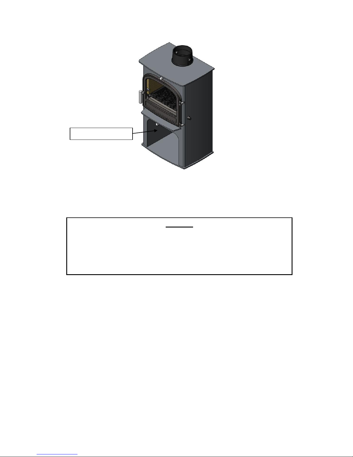
Fuel Storage
Fuel may be placed in the log storage recess underneath the European variant. The logs should be
stacked in such a way that they do not touch the heat shield at the top of the recess.
Important! - Fuel must not be stored underneath the Traditional or Pedestal variants.
Commissioning and Handover
Upon completion of the installation, allow a suitable period of time for any fire cement and mortar to
dry out. A small fire may then be lit and checked to ensure the smoke and fumes are taken from the
stove up the chimney and emitted safely to atmosphere. Do not run the stove at full output for at least
24 hours.
On completion of the installation and commissioning, ensure that the operating instructions and
operating tools for the stove are left with the customer. Ensure to advise the customer on the correct
use of the appliance with the fuels likely to be used on the stove and warn them to use only the
recommended fuels for the stove.
Advise the user on what to do should smoke or fumes be emitted from the stove. The user should be
warned to use a fireguard to BS 6539 in the presence of children, aged and/or infirm persons.
log storage recess
Warning!
The log store recess in European stoves has been designed and tested to satisfy
the requirements of BS EN 13240 with both the ashpan and multi-fuel grate
in place. Under no circumstances should a Euro stove be used without the
ashpan or multi-fuel grate in place. Euro stoves must not be converted to
dedicated wood burning appliances (i.e. no ashpan or multi-fuel grate).
Otros manuales para Norreskoven
1
Tabla de contenidos
Otros manuales de Cocina de Cleanburn


Manuales populares de Cocina de otras marcas


Vermont Castings
Vermont Castings Intrepid 2 Manual de usuario

Italiana Camini
Italiana Camini CLASSICA Guía de inicio rápido

Avalon
Avalon Vashon Avanti DVS FS Manual de usuario

Spartherm
Spartherm ambiente a1 Manual de usuario

Dimplex
Dimplex MCFSTV12AU Manual de usuario

Warmlite
Warmlite WL46040 Manual de usuario