CLEAN ROOM DEVICES CRD221 Manual de usuario
1
CRD221 HEAVY-DUTY TIME DELAY
TUBING EXPANDER
OPERATIONS MANUAL
ORIGINAL INSTRUCTIONS
VERSION 2.5
LAST EDITED 08.11.2022
cleanroomdevices.com

2
Table of Contents
Table of Contents…………………….…………………………………………………………...2
1.0 General Product & Safety Information…………………………………………….…..…3
1.1 Product Information
1.2 Safety Information
2.0 Installation………………………………………………….………………..….………..4
2.1 Air Supply
2.2 Electrical
2.3 Connection Setup
3.0 Operation……………………………………………………………………….…………5
3.1 Jaw Adjustment
3.2 Setting Time Delays
3.3 Expanding Operations
3.4 Jaw Installation and Removal
4.0 Troubleshooting………………………………………….….…………….…………….14
5.0 Maintenance…………………………………………………………………….……….14
5.1 Periodic Cleaning (annually)
5.2 Tools List
6.0 Product Specifications……………………………………………………………….…..15
7.0 Durometer Scale………………………………………………………………………....15
8.0 Wiring Schematic……………………………………………………………….……….16
9.0 Warranty…………………………………..…………………………….………..…..….17
9.1 Warranty
9.2 Warranty period
3
1.0 General Product & Safety Information
1.1 Product Information
•Unit is designed to expand flexible tubing up to a durometer of Shore A 85 (Shore D 35),
including any non-metallic braided materials.
•The minimum/maximum inside tube diameter is 7/16” – 3/4".
•The standard jaw sets are universal and are designed to be used with an inside diameter
range of 7/16" –3/4". Other jaw sets are available that are optimized for a specific size
(see accessories page at www.cleanroomdevices.com or call Clean Room Devices, Inc.).
•The device features simple yet reliable jaw adjustment, which can be made by the
operator.
•The device features a calibrate-able pressure gage conveniently mounted for additional
process control.
•The device features independently adjustable expansion and interval period adjustments
from 0.5-5 seconds, allowing for repeatability of operation.
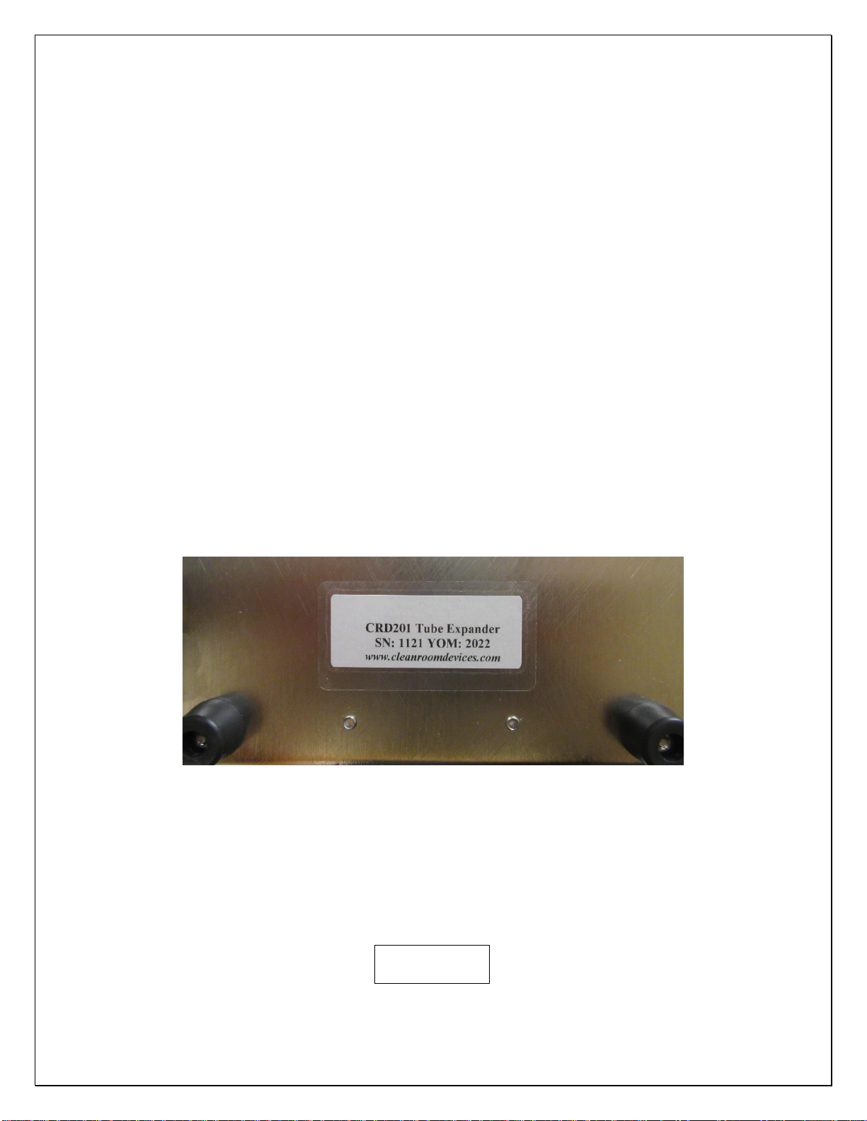
•The serial number for the device is located on the bottom, rear of the base.
Figure 1.1
1.2 Safety Information
•This product uses an air cylinder and foot pedal to pneumatically actuate the expanding
jaws. The unit is not intended to expand anything other than flexible tubing.
WARNING
4
Avoid placing your fingers between the upper jaw block and the air cylinder mounting bracket while
operating unit, sufficient pressure exists to cause personal injury.
Arrows indicate pinch points
2.0 Installation
Ensure all five (5) rubber feet are completely stabilized on your work surface prior to applying
air pressure to the unit.
2.1 Air Supply
•Connect a 1/4” OD air supply hose to the inlet on the pressure regulator. The air supply
should be free of moisture and contaminates and provide a minimum of 100 psi.
•The regulator on the unit should be set to 80-120 psi.
2.2 Electrical
•120 to 240V AC power supply required for operation. The unit will come with the
appropriate 24 VDC power supply.
2.3 Connection setup
•Setting up the connections on the CRD221 is a simple task. Refer to Figure 2.3.1 below
when making all connections to the back panel.
5
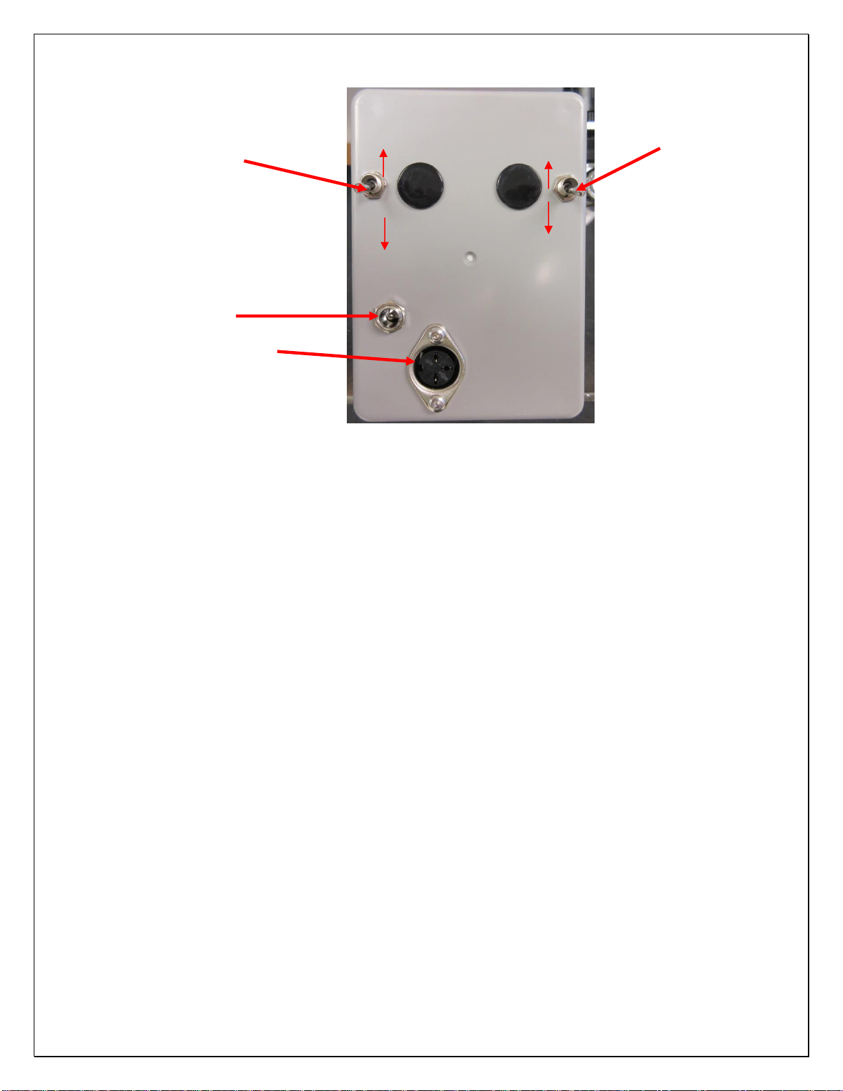
Figure 2.3.1
3.0 Operation
3.1 Jaw Adjustment
•Start by using a 9/16” wrench to loosen the 3/8” hex nut at the bottom end of the lower
jaw support block assembly to adjust the unit for the proper tubing size.
•With A/C power and compressed air attached to the expander, actuate the electric foot
switch which will activate the expander. Adjust the expander lower jaw to the position
you want using the Thumb Wheel Knob. Note that the jaws may be set to remain in the
“open” position using the toggle switch noted in Figure 2.3.1, and triggering the foot
pedal. Make sure the toggle switch is returned to the “off” position, or the jaws will
remain open.
•Locate the lower expander jaw position for your tubing size using the larger thumb-
wheel.
(This adjustment may require fine tuning depending on your tubing I.D., O.D.,
Durometer or material. It is recommended you note or log the jaw gap settings for future
applications, or usage.)
Toggle Switch
Power Jack
Foot Pedal Hookup
On
Off
Jaw Hold-Open
Toggle Switch
On
Off

6
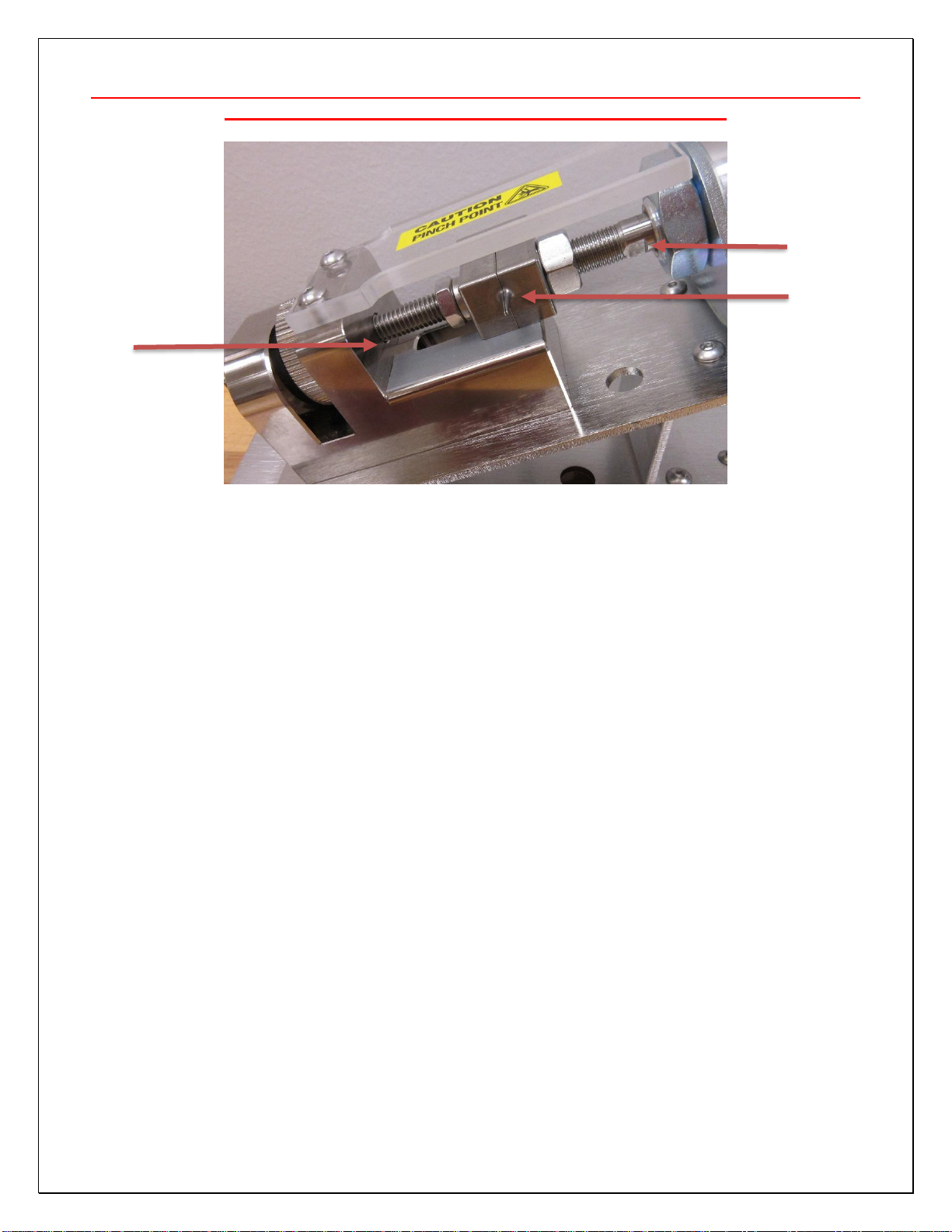
Figure 3.1.1: Jaw Adjustment
•Next, tighten the thumb-wheel against the lower mounting block and secure in place
using the 9/16” wrench to snug the 3/8” hex nut against the bottom of the lower jaw
support block assembly. Be careful that you do not over tighten the nut.
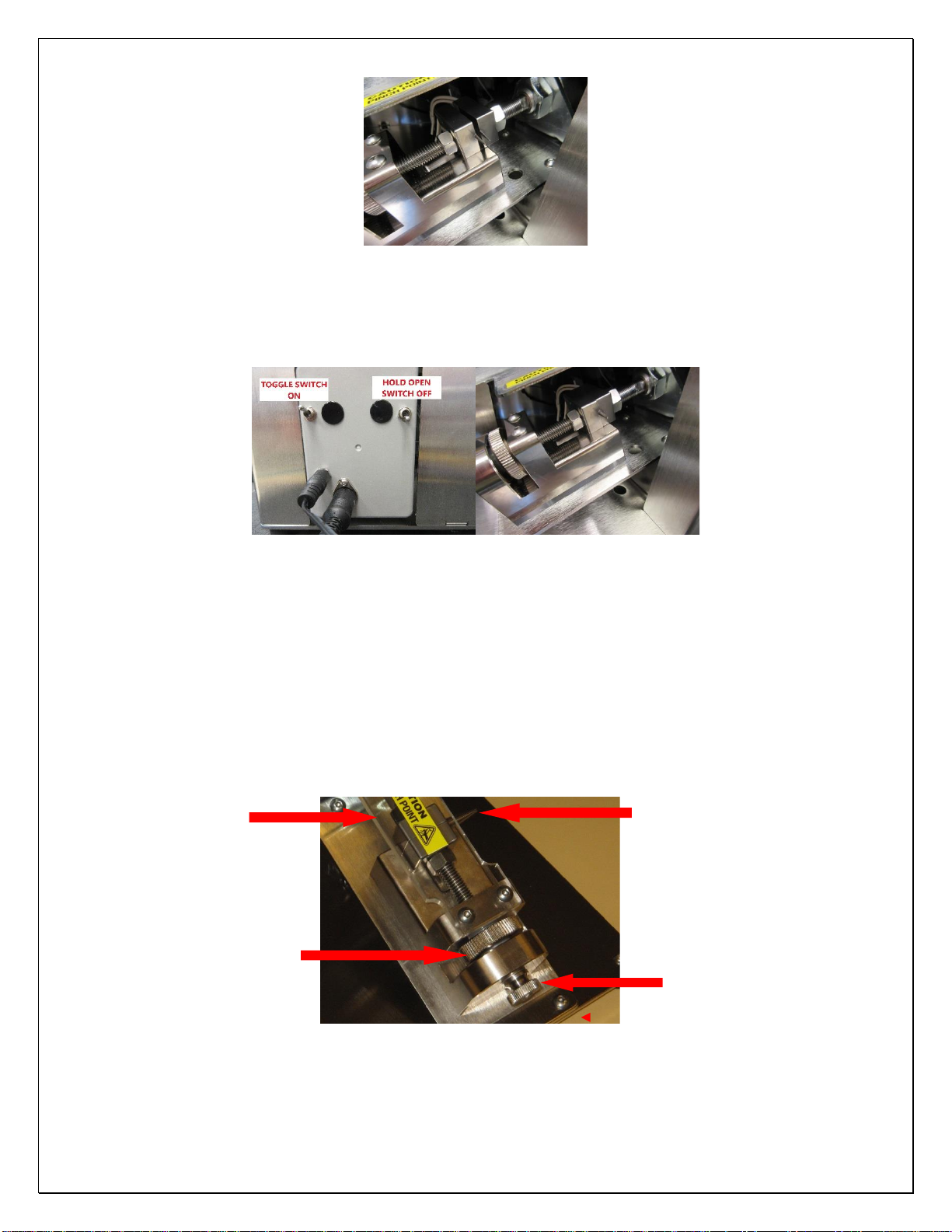
3.1.A Using the Jaw Hold-Open Feature
•A Jaw Hold-Open switch has been installed on the tubing expander. This makes setting
the gap between the jaws much simpler.
1) With the toggle switch in the “ON” position, flip the jaw hold-open switch to the
“ON” position (UP).
Figure 3.1.A.1 Figure 3.1.A.2
2) Use the foot pedal to trigger the cycle. The upper jaw will retract and remain open.
Thumb Wheel
Lock Nut
7
Figure 3.1.A.3
3) Flip the jaw hold-open switch to “OFF” position (DOWN) and the upper jaw will
return to the non-expanded position.
Figure 3.1.A.4 Figure3.1.A.5
Note: Several expanding actions may be necessary to effectively expand the end of
the tube for the fitting/connector to slide in. Each time you expand the tubing
remember to rotate the tubing 90 degrees on the jaws.
•Quickly insert the component or tube connector before the tubing regains its original
size.
Safety Guard Jaw Set
Thumb Wheel Lock Nut
3.2 Setting the Time Delays

8
•The CRD201 expansion operation is designed to let the operator expand each piece of
tubing twice. After the first expansion, the jaws will close and the operator rotates the
tube 90 degrees and the jaws will automatically expand again. This ensures that the
tubing is expanded in a uniform fashion, and not deformed in only one direction. To
assist with this 2-step expansion operation, there are two time delay relays on the unit.
oExpansion Time –This setting adjusts the rate (0.5-5.0 seconds) at which the
tube expansion occurs. The rate at which the tube is expanded is critical to
prevent tearing. Some stiffer tubing might need a longer expansion time, while
softer tubing can be expanded rapidly.
oInterval Time –This setting adjusts the time delay rate (0.5-5.0 seconds) at
which the jaws will cycle. It is adjusted to allow the operator to rotate the tubing
90 degrees at a comfortable pace between expanding.
•Remove the hole plugs with a screwdriver on the rear cover to gain access to the Time
Delay adjustment pots. Figure 3.2.1
Figure 3.2.1 Removing Access Hole Plugs
•Using a small Phillips drive screwdriver adjust the Time Delay relays. Figure 3.2.2
Turn the adjustment screw clockwise (to the right) to increase the delay. Turn the
adjustment screw counter-clockwise (to the left) to decrease the delay.

9
Figure 3.2.2 Adjusting the Expansion Time Pot
•Figure 3.2.3 below shows the CRD201 with the rear cover removed, as well as the
location of both time delay adjustments on the time delay relay:
Top of unit
Figure 3.2.3
Interval Time
Adjustment
Expansion Time
Adjustment

10
3.3 Expanding Operation
•To adjust the jaws for the size tubing to be expanded you need to loosen the 3/8” hex nut
(Lock Nut.)
•With A/C power and compressed air attached to the expander, actuate the electric foot
switch which will activate the expander. Adjust the expander lower jaw to the position
you want using the Thumb Wheel Knob. Note that the jaws may be set to remain in the
“open” position using the toggle switch noted in Figure 3.3.1, and triggering the foot
pedal. Make sure the toggle switch is returned to the “off” position, or the jaws will
remain open.
•Turning the Thumb Wheel clockwise will increase the jaw expansion size, counter
clockwise will decrease the jaw expansion size. This adjustment may require fine tuning
depending on your tubing I.D., O.D., durometer and/or material.
•Once you have the expansion size you want tighten the Lock Nut to secure the
adjustment.
•Place the tube over the ends of both expander jaws and hold firmly in place.
•Actuate the Tube Expander by pressing the electric foot switch.
•Rotate the tubing 90 degrees on the jaws and actuate the Tube Expander by pressing the
electric foot switch again. Failure to do so may result in uneven expansion and/or
damaged tubing!
Note: Several expanding actions may be necessary to effectively expand the end of
the tube for the fitting/connector to slide in. Each time you expand the tubing
remember to rotate the tubing 90 degrees on the jaws.
•Quickly insert the component or tube connector before the tubing regains its original
size.
Tabla de contenidos
Otros manuales de Equipos industriales de CLEAN ROOM DEVICES


