Christini AWD Manual de usuario

Service Manual
Page 1
Service Manual
Christini Technologies, Inc.
421 N. 7th Street Suite 200
Philadelphia, PA 19123
215.351.9895
215.351.9896 fax
info@christini.com
Version 1.3

Service Manual
Page 2

Service Manual
Page 3
Table of Contents
Introduction; Tools you’ll need 4
AWD Bike Detail Illustration 5
Bike Disassembly Flowchart 6
White Brothers AWD Fork Removal 7
White Brothers AWD Fork Drive Shaft Maintenance 8
AWD Drive Shaft Removal and Installation 10
AWD Engagement Clutch Detail 13
AWD Engagement Switch Detail 16
AWD Engagement Cam Detail 17
Rear Suspension Detail 18
AWD Bearing Maintenance 19
Routine Maintenance Schedule 20
General Notes 21
AWD Lubrication Guide 22
AWD Troubleshooting 23
Appendix:
Christini AWD Limited Warranty 24
Christini Owner’s Registration Card 25
Front Hub Maintenance 15
Service Manual
Page 4
The CHRISTINI AWD consists of a patented lightweight, inter-
nalized, shaft-driven system that allows the rider to engage
both wheels for additional power when there is "wheel slip".
With the simple flip of a handlebar-mounted switch, the AWD
system provides increased control, traction and stability on
slippery or loose surfaces and unmatched power to climb
steep hills.
Simply stated, when the rear wheel slips — the front wheel
grips.
Congratulations! You own an All Wheel Drive Bicycle
• Allen Wrench Set
• 2, 2.5, 3, 4 with short end (supplied), 5, 6 millimeter
wrenches
• Plastic faced hammer or a rubber mallet
• Large flat bladed screwdriver & small flat bladed screwdriver
• Torx style wrench - included with disk brake set
• 10 millimeter box wrench
• Pair of needle-nose pliers
• Thread Retaining Compound:
• “Blue” Loc-tite 242 Removable Strength
• “Red” Loc-tite 262 Permanent Strength
The Tools You Will Need for Maintenance
Service Manual
Page 5
Page 5
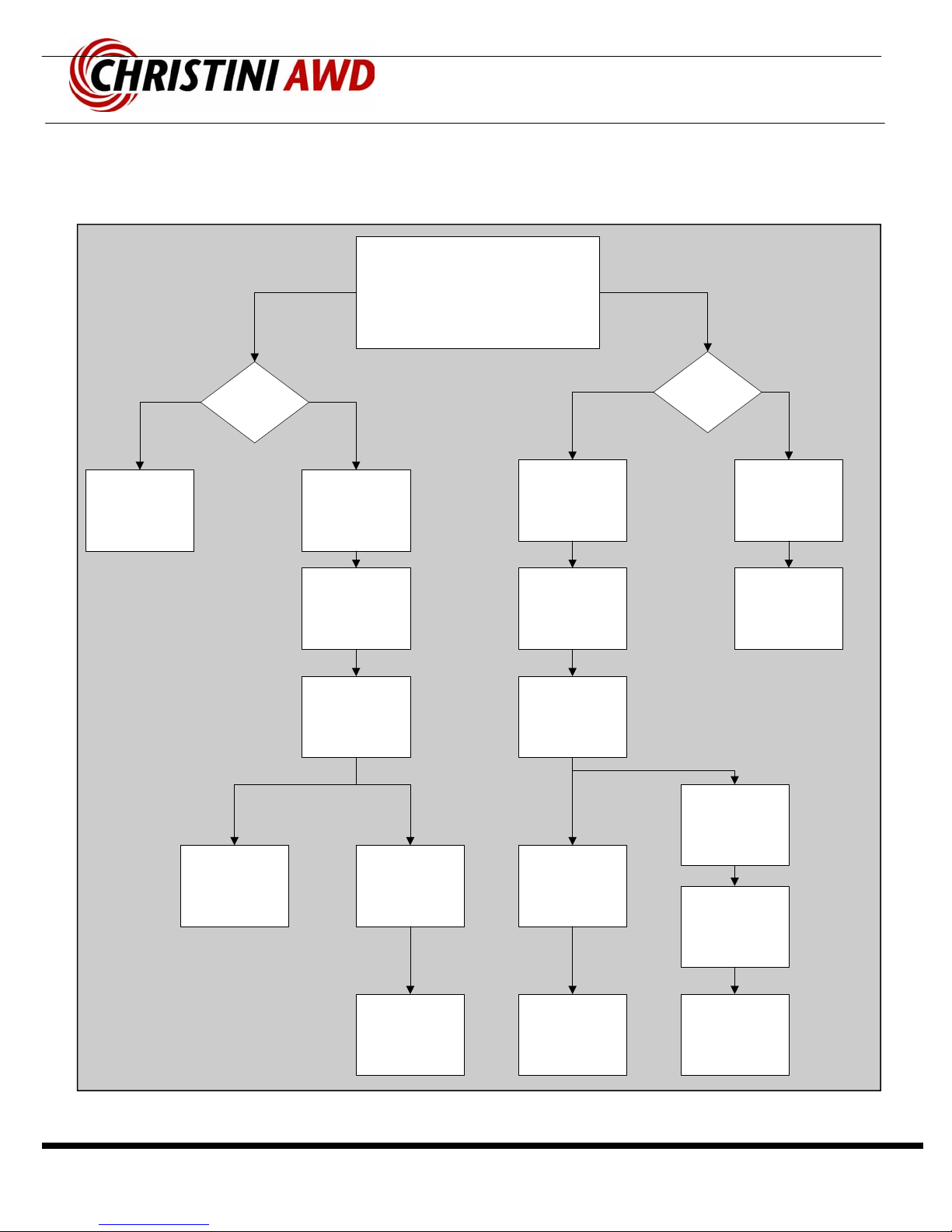
AWD Detail Illustration
Service Manual
Page 6
Page 6
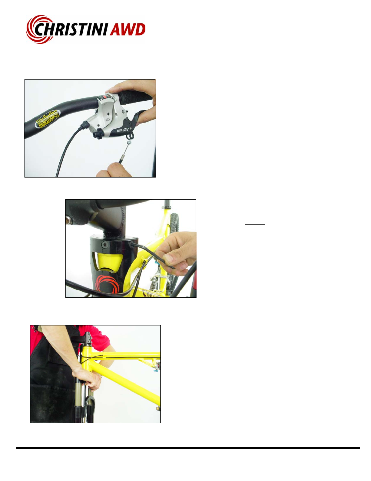
Bike Disassembly Flowchart
Remove Fork
Remove
Front Wheel
Remove Front
Bevel Gear
Remove Chain
Crown Cover
Remove Front
Pinion
Remove
Rear Wheel
Remove
Clutch
Remove Rear
Bevel Gear
Remove Shock
Remove
Suspension
Link
Remove Front
Drive Shaft
Remove Rear
Pinion
Remove Rear
Drive Shaft
Remove Pivot
Bolts
Remove Rear
Triangle
All Wheel Drive Bike
Disassembly Process
Separate the
Front and Rear
Driveshafts
Remove
Headtube
Gear and
Sprocket Shaft
Remove
Power
Transfer Chain
Remove Front
Driveshaft
Service Manual
Page 7
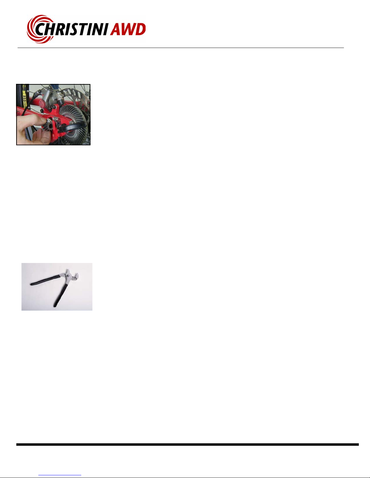
• Remove the front wheel. The fork legs may
need to be pulled apart slightly, since there is
a 1 mm indent on the non-disc brake side of
the front hub axle. This indent locates the
front bevel gear and provides support during
heavy AWD loading.
• Remove the front disk brake cable at the
lever—or remove the front disk brake caliper.
• Remove the three M6 bolts, located just
above the headtube on the front plate, that
attach the steering link to the upper steering
clamp.
• Warning—DO NOT use the rounded Bohndus
end of the Allen wrench when first loosening
the bolts. You will strip the hex head of these
bolts.
• After these three bolts have been removed,
the fork can be pushed down out of the head-
tube of the bicycle. If necessary, use a plastic
hammer to tap the fork out. Hit the hammer
on the top of the brake arch to avoid damag-
ing the forks valves.
• Please refer to the White Brother’s AWD Fork
Owner’s Manual to service or adjust the front
suspension. (If lost see www.WhiteBros.com
for details)
Installation:
• Slide Lower steering tube into the support bear-
ings in the headtube.
• Tap the fork into place with a plastic hammer.
Do not tap the crown cover.
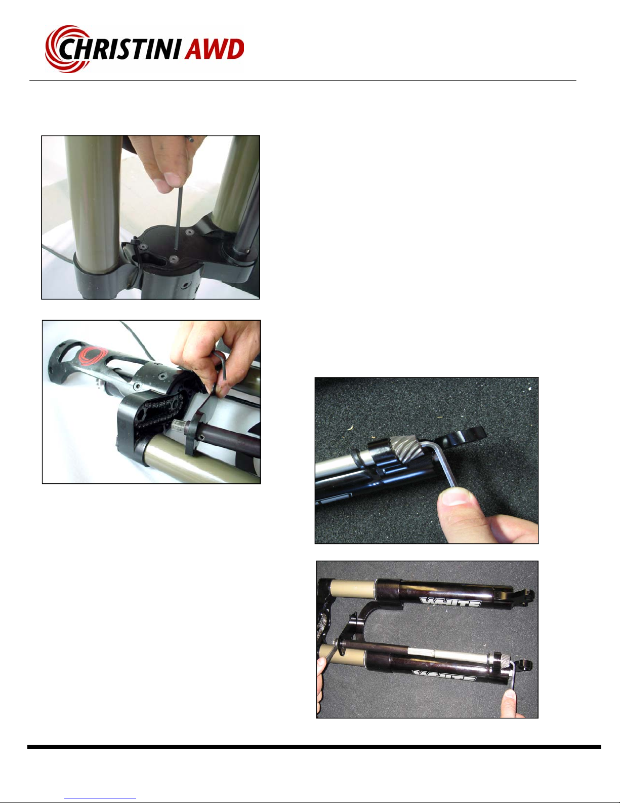
Custom White Brothers AWD Fork Removal
Service Manual
Page 8
Fork Driveshaft Maintenance
Removal
• Remove the four countersunk M4 screws under the
crown of fork which hold the crown cover plate in
place.
• Remove the Crown-Cover plate. Slide the Upper
Front driveshaft and the crown cover plate down, as
shown, towards the dropouts. The Upper Front
Driveshaft will compress and slide on the splined
portion of the drive shaft.
▪Remove the fork drive shaft capture bolt. It is an M6 bolt
on the end of the fork drive shaft located under the pinion gear.
▪To loosen the bolt, use the supplied short-end 4mm Allen
wrench to hold the bolt in position while turning the hex piece
of the driveshaft counterclockwise (from the top of the fork
looking down), with a 10mm box wrench.
▪TIP: If the driveshaft is stuck in the gear, loosen the bolt
halfway and then gently tap the blot head with a hammer to
free the driveshaft.
Service Manual
Page 9
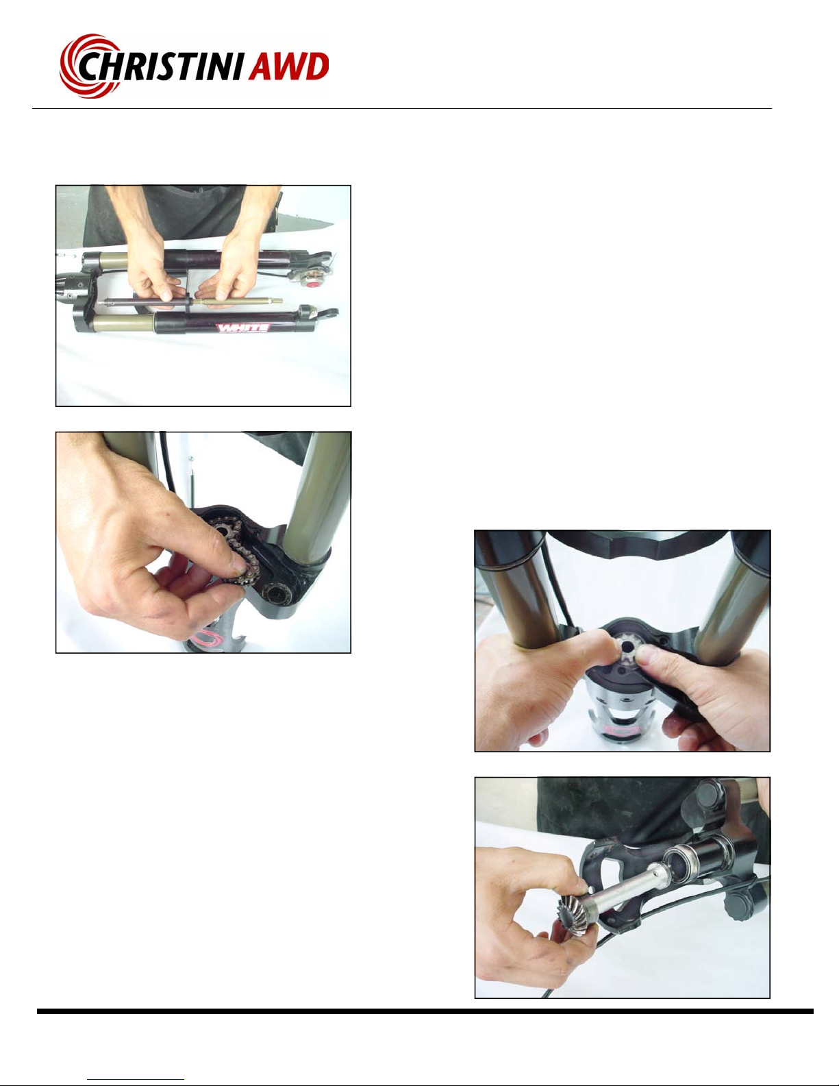
Fork Driveshaft Maintenance
Installation:
▪Insert the drive shaft into the steering tube, sprocket first,
until the miter gear is fully seated on its sealed bearing
support.
▪Loop the chain around the shaft sprocket and the floating
cog. Press the cog into the bearing.
▪Press the upper hex portion of the driveshaft into the cog
and slide the chain crown up into place.
▪Use removable threadlocker when re-installing the crown
cover screws.
▪Use removable threadlocker on the pinion bolt.
Removal:
▪Slide the two sections of the front drive shaft together.
▪The chain crown cover can slide off at this point.
▪The pinion gear can also be removed at this point.
▪Remove the floating cog and power transfer chain from
the internal section of the chain crown.
▪Use your thumbs to press the center sprocket up through
the lower steering tube.
▪Carefully pull the drive shaft out of the steering tube.
Service Manual
Page 10
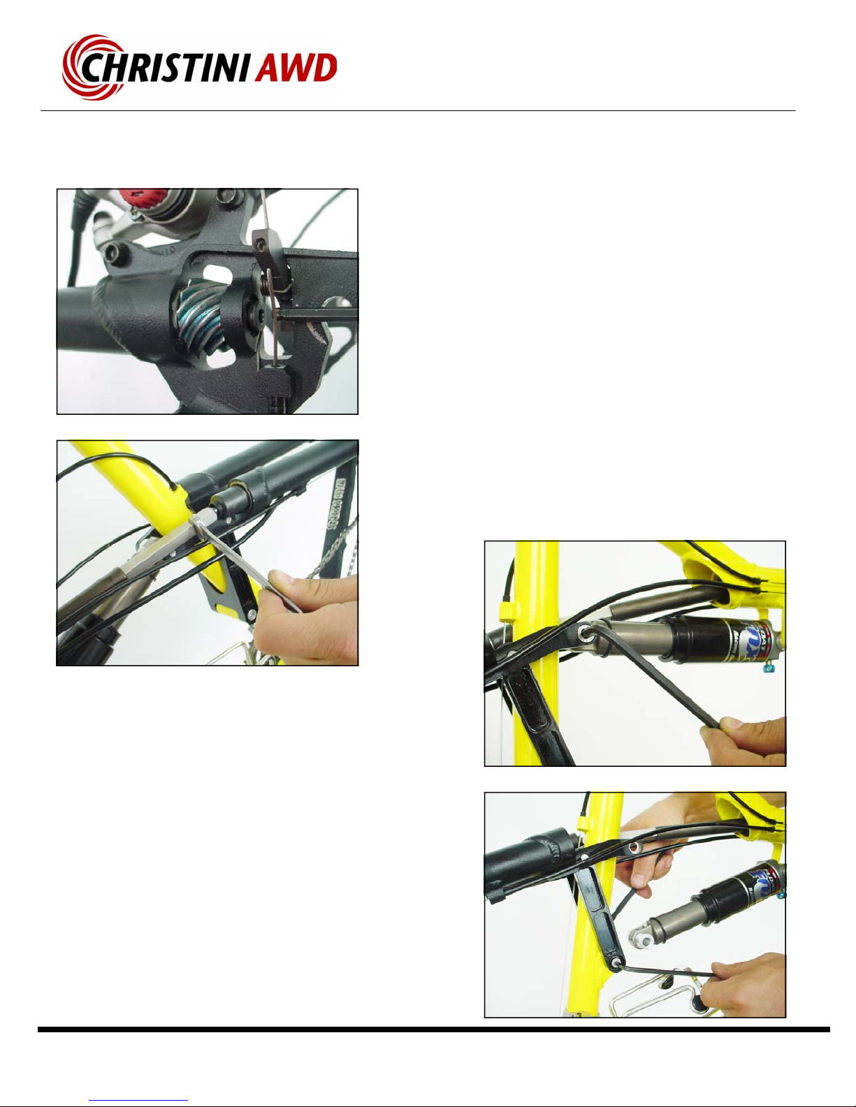
AWD Frame Drive-system Maintenance
Re-assembly:
▪Slide the rear pinion into the slot and then drop the rear
drive shaft down into the female spline on the pinion.
▪Apply removable threadlocker to the M6 bolt and tighten
by holding the bolt with a wrench and then spin the drive
system clockwise to tighten.
▪Install the rear shock mount bolt and the rear shock.
Removal:
▪Remove the M6 capture bolt from the rear pinion assembly on
the rear bevel dropout. Use the supplied short-end Allen Wrench to
hold the bolt while spinning the drive system by hand to remove the
bolt.
▪If necessary, use a 10mm wrench to spin the square spline
section of the drive system to help loosen the bolt.
▪Remove the rear shock mount bolt, and then slide the shock
out from between the Top Yoke, as shown.
▪TIP: Be careful not to chip the frame paint with the suspension
link when the rear triangle swings backward.
Tabla de contenidos


