Castle, Inc. TSM-12 Manual de usuario

CASTLE INC
Owners Manual
TSM-12

CASTLE,INC TSM‐12OWNERSMANUALV1.0 Page2of23

CASTLE,INCTSM‐12OWNERSMANUALV1.0 Page3of23
Table of Contents
1INTRODUCTION.............................................................................................................................4
2MACHINE SAFETY.........................................................................................................................5
2.1 SAFETY RULES..........................................................................................................................5
2.2 INVENTORY................................................................................................................................6
2.3 TOOLS.......................................................................................................................................8
2.4 MACHINE REQUIREMENTS ..........................................................................................................8
3SETTING UP YOUR TSM-12 .........................................................................................................9
4OPERATING INSTRUCTIONS.....................................................................................................13
4.1 GENERAL INFORMATION ...........................................................................................................15
4.2 DUST COLLECTION...................................................................................................................15
5MACHINE ADJUSTMENTS..........................................................................................................17
5.1 POCKET HOLE ALIGNMENT.......................................................................................................17
5.2 WEB ADJUSTMENT...................................................................................................................18
5.3 ADJUSTING FOR THINNER MATERIAL.........................................................................................18
6SERVICE AND MAINTENANCE ..................................................................................................19
6.1 ROUTER BIT REPLACEMENT .....................................................................................................19
6.2 PILOT BIT REPLACEMENT.........................................................................................................20
6.3 MOTORS AND BITS...................................................................................................................22
6.4 SERIAL NUMBER LOG...............................................................................................................22
7WARRANTY INFORMATION .......................................................................................................23

CASTLE,INC TSM‐12OWNERSMANUALV1.0 Page4of23
1 Introduction
Thank you for making the Castle TSM-12 the latest addition to your shop. Since 1985 our goal
has been to manufacture and develop machines that make cabinetmaking and casework easier,
faster and more profitable for the woodworker. This machine represents our commitment to your
productivity. Castle machines are made in Petaluma, California and are manufactured to the
highest standards using local vendors wherever possible.
This instruction manual is intended for use by anyone setting up or servicing this machine. It
should be kept available for immediate reference so that all operations can be performed with
maximum efficiency and safety.
Note: Do not attempt to perform maintenance or operate this machine until you
have read and understand the information contained in this manual.

CASTLE,INCTSM‐12OWNERSMANUALV1.0 Page5of23
2 Machine Safety
The Castle TSM-12 was designed with operator safety as a priority. This machine was carefully
packaged for shipment at our factory. Upon receipt of the machine, inspect for shipping damage.
Report any damage IMMEDIATELY to the freight company, your Castle dealer and to Castle,
Inc. DO NOT attempt to operate the machine if you observe any physical damage. Contact
Castle, Inc. at 800.282.8338 for instructions.
2.1 Safety Rules
The Castle Model TSM-12 Bench-top Pocket Machine was designed with operator safety as a
priority, which is why Castle highly recommends the following:
1. Do not plug machine in until ready to operate.
2. Always wear eye protection when operating or servicing mechanical equipment.
3. Always wear hearing protection when the machine is in operation.
4. Always verify that the drill and router bits are securely tightened.
5. Do not at any time put your hand under the clamp guard, in the path of router bit or drill
bit.
6. Familiarize yourself with the clamping action, routing and drilling functions before plug-
ging the machine into electrical power supply.
7. Always be sure to securely clamp stock before routing or drilling any material.
8. Always plug TSM-12 into 110 volt grounded power outlet.
9. Never allow machine to get wet or be used in a wet environment.

2.2 Inventory
Your TSM-12 will pocket any material you would normally rout. It is designed for material from
½” to 1 ½”. Use of materials thinner than ½” is not recommended. Every TSM-12 machine is
factory adjusted. If you should find a small amount of sawdust in the bottom of your TSM-12,
please don’t be alarmed. This is an indication that your machine has been factory tested prior to
shipping.
Within your Castle machinery shipment, you should receive the following:
CASTLE,INC TSM‐12OWNERSMANUALV1.0 Page6of23
Fig 1
CASTLE TSM-12 BENCH-TOP POCKET MACHINE SHIPPING INVENTORY
Part # Part Descri
p
tion Qt
y
---- TSM-12 Case 1
E21617 Router Motor - Bosch 2.0h
p
#1617 1
E21610 Drill Motor - Bosch Colt 1.0h
p
#PR10E 1
S90011 TSM-12 O
p
erator Manual with Warrant
y
Activation Card 1
---- - Bottom Tem
p
late & Hardware
(
3 cli
p
s & 3 screws
)
1
V
11001 TSM-12 Work To
p
1
H11001 Non-Sli
p
Machine Feet 4
---- Hardware Pack
(
ima
g
e of contents and inventor
y
below
)
1

CASTLE,INCTSM‐12OWNERSMANUALV1.0 Page7of23
CASTLE TSM-12 BENCH-TOP POCKET MACHINE HARDWARE PACK
Part # Part Descri
p
tion Qt
y
F51628 5/16” - 18 Nuts 4
F44114 ¼ - 20 x 1” Flathead Machine Screws 4
F01420 ¼ - 20 Locknuts 4
B02964 9/64” TiN Coated Premium Drill Bit w/ ¼” Shank 1
B00338 3/8” Solid Carbide 3-Flute Premium Router Bit 1
D50038 3/8” Collet 1
B00622 6” S
q
uare Driver Bit 1
--- Bosch Collet Wrenches
(
for Bosch 2.0h
p
#1617
)
2
T00532 5/32” Hex Ke
y
1
O00234 Bit Gau
g
e 1
Fig 2

2.3 Tools
To complete assembly of Castle machine, you will require the following tools:
(1) 7/16” wrench or ratchet
(1) ½” wrench or ratchet
Fig 3
2.4 Machine Requirements
ELECTRICITY:
Your TSM-12 is designed to run on a 110 volt -15 AMP standard 3 prong power supply. 2 prong
power adapters are not recommended for use on this machine and could cause electric shock to
the user. Be sure your unit is properly grounded. See a qualified electrician if you are in question
about your electrical safety compliance.
CASTLE,INC TSM‐12OWNERSMANUALV1.0 Page8of23

CASTLE,INCTSM‐12OWNERSMANUALV1.0 Page9of23
3 Setting Up Your TSM-12Setting Up Your TSM-12
Caution: Always use eye and hearing protection when operating power equipment.
1. Remove the machine from the carton and plastic over-wrap and
place on its back as shown (Fig 4). Be careful to place it on a
clean surface free of debris to avoid
damage to the finish.
Caution: Remove Foam pads from between
the case sides and router carriage before
running the machine (Fig 5).
Fig 4
Fig 5
2. Secure the (4) non-slip machine feet to the machine using a ½” wrench and (4) 5/16”-18
nuts (Fig 6).
3. Unpack the Bosch Colt #PR10E trimmer motor, collet and collet
wrenches from box. DO NOT UNTIE THE POWER CORD! Insert the
Castle Premium drill bit until the tapered portion of the shank is ap-
proximately flush with the collet opening. While holding the spindle
lock button, secure the drill bit with the collet wrench (Fig 7). Toggle
the motor switch to the “ON” position.
Fig 6
Fig 7
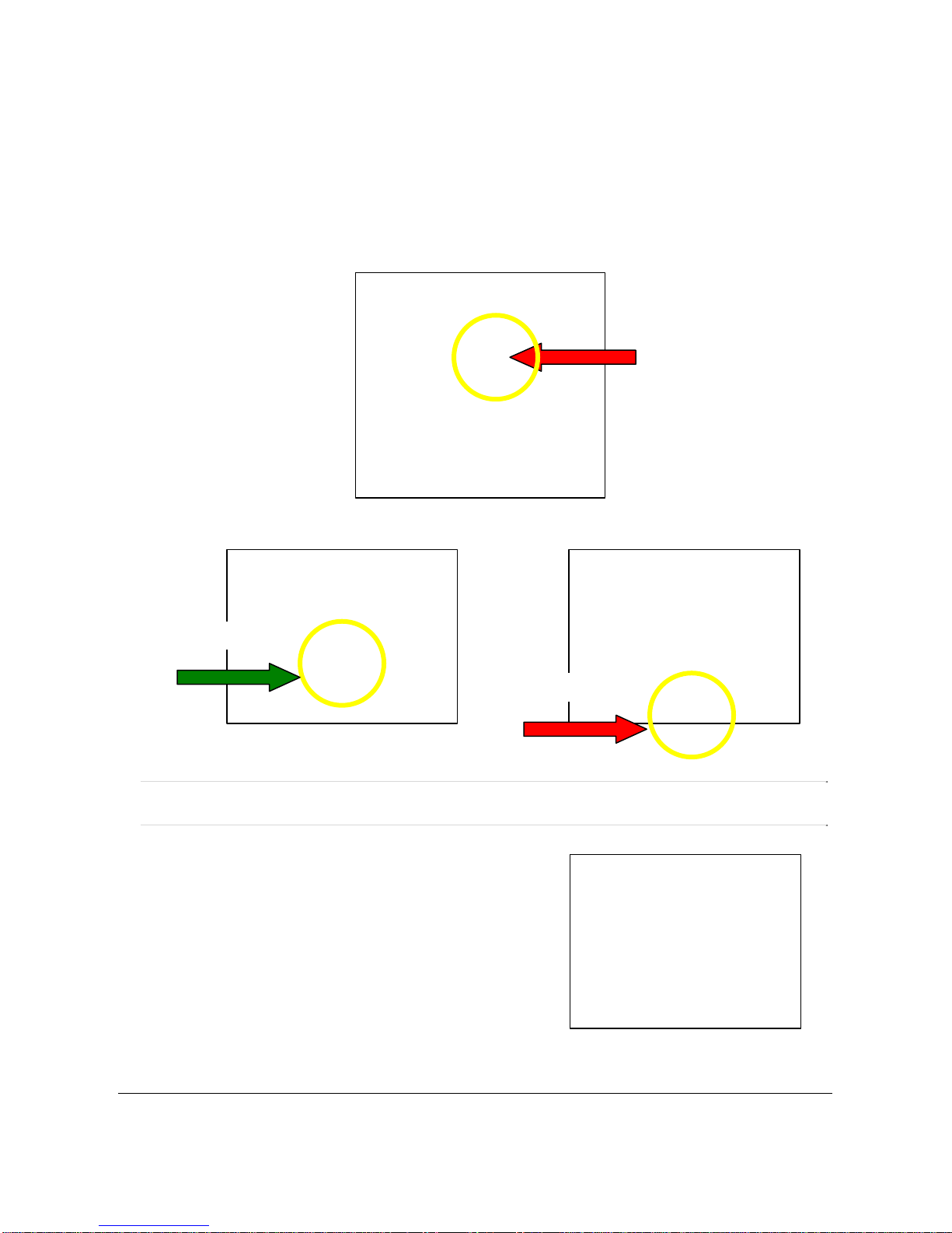
4. To install your drill motor it should be rotated so that the vertical feature on the motor
cowling is in contact with the Motor Stop Tab on the small motor carriage. (Fig 8).
Align the drill motor with the small motor carriage as shown. (Fig 9) You DO NOT
want a gap between the tab on the motor carriage and the drill motor cowling. (Fig
10).
Motor Stop
Tab
Fig 8
Fig 10
Incorrect
Correct
Fig 9
Note: Failure to properly align the drill motor in the small motor carriage may result
in pilot holes that are off-center.
5. Tighten the hose clamp with a slotted screw driver
(Fig 11).
Fig 11
CASTLE,INC TSM‐12OWNERSMANUALV1.0 Page10of23
Tabla de contenidos


