Cansec Canlan Manual de usuario

Canlan
INSTALLATION MANUAL
August 2014


CanLan Page 3 of 31
Installation Manual August 2014 • Rev. 1.2
Table of Contents
Introduction ...................................................................................................................4
Overview ........................................................................................................................5
RJ45 Connector and Status LEDs.........................................................................5
Power Input...........................................................................................................6
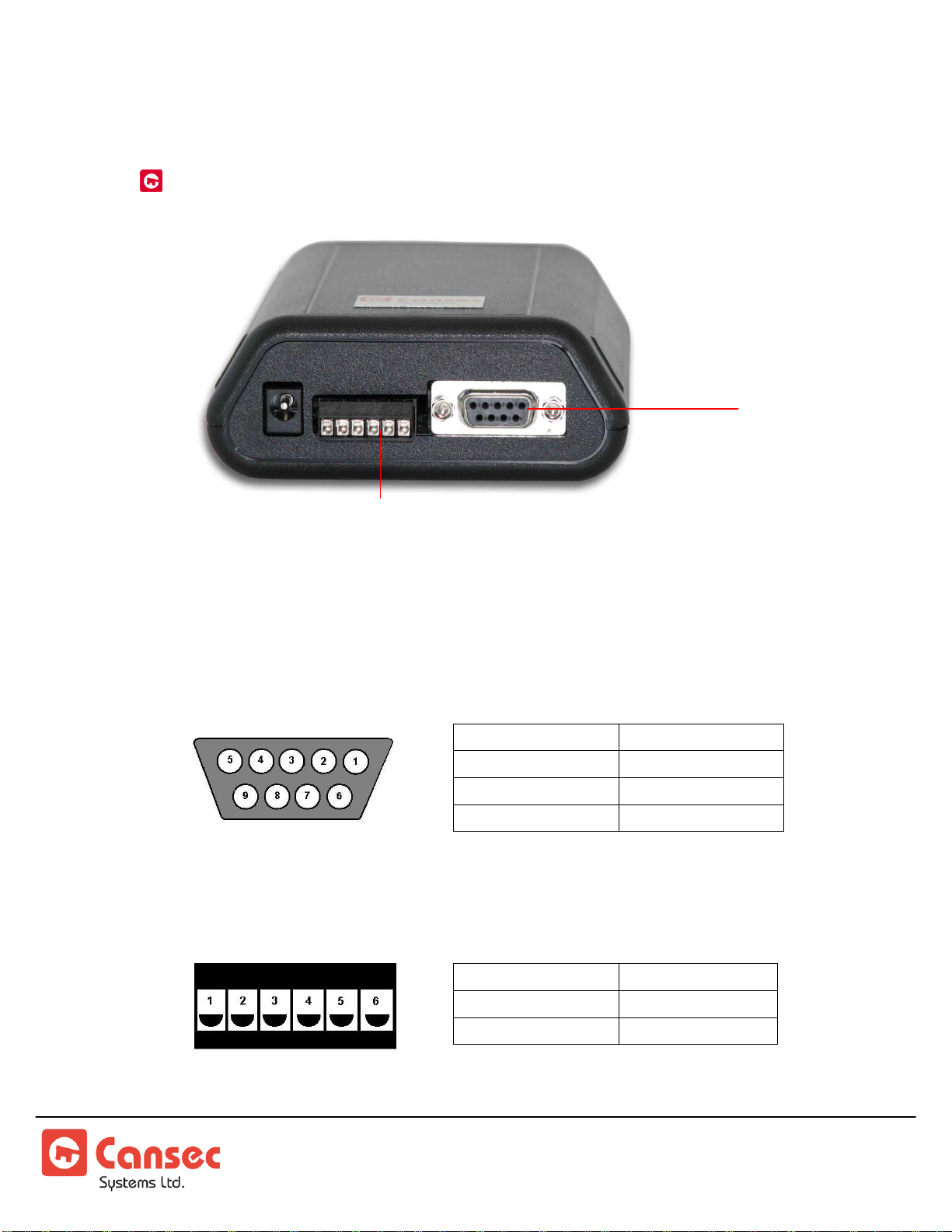
RS232 / RS485 Connectors..................................................................................7
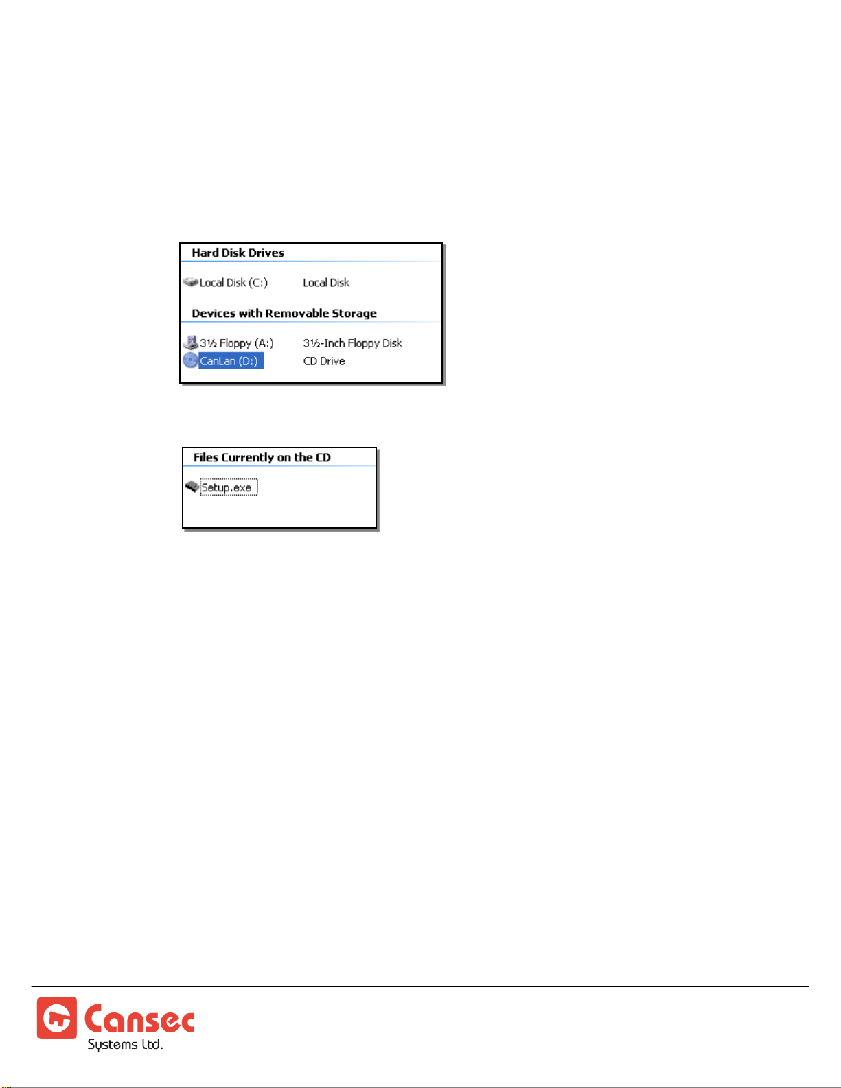
Installing the Canlan Software.....................................................................................8
Connecting the Canlan to the PC.................................................................................9
Serial Connection..................................................................................................9
Network Connection..............................................................................................9
Making a Connection..................................................................................................11
Setup and Configuration ............................................................................................14
Address Configuration.........................................................................................14
Operational Mode................................................................................................15
Remote Diagnostics ............................................................................................16
Serial Interface....................................................................................................17
Saving the Settings .............................................................................................17
Commands..........................................................................................................18
Connecting the Canlan to a Control Panel................................................................19
Wiring (SmartLock)..............................................................................................20
Wiring (Maestro)..................................................................................................21
Configuring Host Software.........................................................................................22
Maestro ...............................................................................................................22
SmartLock Pro.....................................................................................................26
Determining MAC Addresses.....................................................................................29
Appendix I....................................................................................................................31
Troubleshooting a Connection.............................................................................31
Copyright 2008 Cansec Systems Ltd.
All rights reserved.

CanLan Page 4 of 31
Installation Manual August 2014 • Rev. 1.2
Supports RS485 communications
Supports up to 16 CP40 control panels
Supports up to 30 SmartLock Pro control
panels
Onboard communication application
conserves bandwidth
Minimal impact on shared networks
Introduction
The Canlan network communications device provides seamless network
connectivity for Cansec access control products. The CanLan supports up to
16 CP40 or 30 Smartlock®control panels. On Maestro systems, network
traffic only occurs when events or commands need to be relayed between the
host and the control panels. Bandwidth is conserved through a complete
implementation of the CP40 protocol on the control panels.
A standard 10 Base-T network
connection is provided for interfacing
purposes. This allows the use of low
cost Category 3 (or higher)
unshielded twisted pair wiring,
typically present in most LAN
environments. With onboard
processing and low bandwidth usage,
the Canlan offloads work from host
software with minimal impact on
shared networks.
Key Features

CanLan Page 5 of 31
Installation Manual August 2014 • Rev. 1.2
Overview
The Canlan consists of:
5 status LEDs
3 interface connectors
1 AC adaptor plug*
*an access panel's battery backup can also be used (see the section on Power)
RJ45 CONNECTOR AND STATUS LEDS
The front of the Canlan (shown below) houses the RJ45 interface and the
status LEDs.
A
RS232 Port Activity LED
flashes when there is activity on the RS232
interface
B
RS485 Port Activity LED
flashes when there is activity on the RS485
interface
C
Link Activity LED
flashes on reception/transmission of
Ethernet frames
D
Link Status LED
indicates an active connection between
Canlan and hub when lit
E
Power LED
indicates that the Canlan is on when lit
F
10 Base-T Connector
standard 10 Base-T RJ45 connector for use
with a crossover or straight through cable
B
A
F
C
D
E

CanLan Page 6 of 31
Installation Manual August 2014 • Rev. 1.2
POWER INPUT
There are two options for providing power to the Canlan:
1. AC input
2. 12 VDC input
AC Adaptor
The supplied AC power adapter can be plugged into the AC adaptor
connector on the back of the Canlan. NOTE: a power outage will result in a
20-30 loss of connectivity to the device.
12 VDC Battery Backup (recommended)
The Canlan can be wired via the RS485 header connector to a Cansec access
control panel's 12 VDC output. Wiring the Canlan to a panel with battery
backup will prevent the unit from being reset during an AC power failure.
AC Adaptor
Connector
RS485 Header
Connector
GND
(–) NEG
12 VDC
(+) POS

CanLan Page 7 of 31
Installation Manual August 2014 • Rev. 1.2
RS232 / RS485 CONNECTORS
RS232 Female DB9 Connector
The female DB9 connector supports a 3-wire interface with the following
pin-outs:
1. Not Used
2. RX
3. TX
4. Not Used
5. Gnd
6. Not Used
7. Not Used
8. Not Used
RS485 Header Connector
The RS485 header connector has the following pin-outs:
1. RS485A
2. RS485B
3. GND*
4. Reserved
5. Reserved
6. +12V DC*
*use when wiring Canlan to battery backup
RS232 Female
DB9 Connector
RS485 Header
Connector

CanLan Page 8 of 31
Installation Manual August 2014 • Rev. 1.2
Installing the Canlan Software
1. Insert the mini CD into your computer's CD drive.
2. Go to My Computer and double-click your computer's CD drive.
3. Double-click Setup.exe.
4. Follow the installation instructions.

CanLan Page 9 of 31
Installation Manual August 2014 • Rev. 1.2
Connecting the Canlan to the PC
For first-time configuration, a serial connection is most often used, but the
following outlines how to connect the Canlan to the PC using either of the
following methods:
Serial Connection
Network Connection
SERIAL CONNECTION
1. Connect the CanLan to the PC using the DB9 data cable provided.
2. Continue to the Making a Connection section on page11.
NETWORK CONNECTION
Before connecting the CanLan and the PC using a network connection, you
must first change the host PC's IP address.
1. Go to Start > Control Panel >Network Connections.
2. Right-click on the PC's ethernet
connection and choose Properties from
the context menu.
NOTE: You may first have to disable any
wireless network connections.

CanLan Page 10 of 31
Installation Manual August 2014 • Rev. 1.2
3. Select Internet Protocol (TCP/IP) from
the list and press the Properties button.
4. Write down your current settings.
5. Select Use the following IP address
and enter:
IP address = 10.0.0.1
Subnet Mask = 255.255.255.0
Default Gateway = 10.0.0.1
6. Click OK.
7. On the Local Area Network Properties
window, click OK.
Tabla de contenidos


