CANNY S-35 Manual de usuario
CANNY S-35
Full$Automatic$Banknote$Strapping$Machine$ $
Service Manual

TABLE OF CONTENTS
Part A: Service Manual
I. Appearances............................................................................................1
II. PCB Sockets and Connection Parts .....................................................12
III. Description of Strapping Steps.............................................................14
IV. PCB Electric Circuit Diagram..............................................................15
V. Components List ..................................................................................16
Part B: Disassembly and Troubleshooting
I. Required Tools .....................................................................................17
II. Removing Main Cover..........................................................................19
III. Replacing MH4 and MH5....................................................................23
IV. Replacing MH Motor............................................................................24
V. Replacing Top Tape Guide Set.............................................................27
VI. Replacing Front Tape Feeding Motors.................................................33
VII. Removing Movable Front Tape Feeding Set........................................41
VIII. Removing Photo Sensor / Cam Driving Assembly Set.......................43
IX. Replacing Inner Start Button................................................................47
X. Replacing Pressing Motor MP and Compressor Assembly Set...........48
Part C: Adjustment, Cause, and Solution Guide
I. Adjustments and Testing ......................................................................53
II. Troubleshooting....................................................................................65

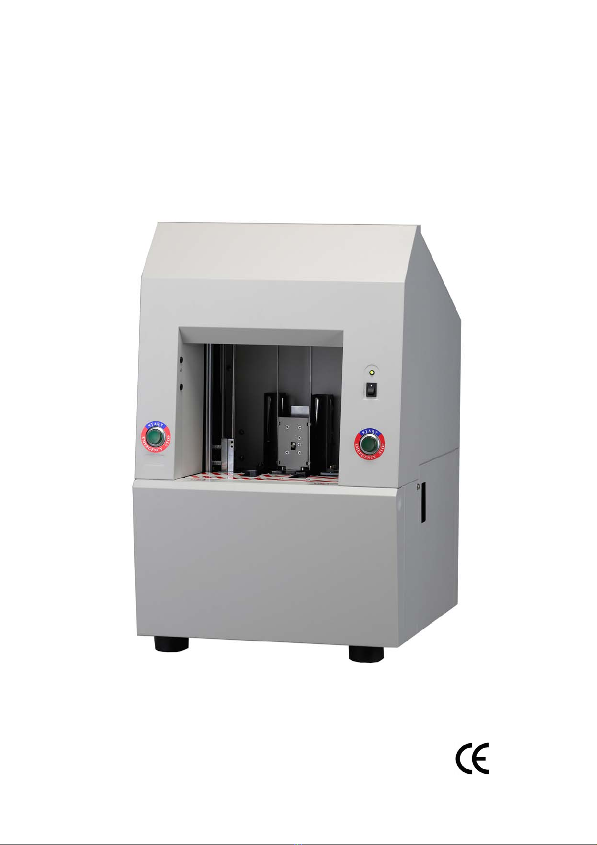
I. Appearances
Fig.1 Front View of Tape Feeding Assembly Set
(MF 1 and MF 3) (F07)
Fig.2 Side View of Tape Feeding Assembly Set
(MF 1 and MF 3) (F07)
1. Tape Feeding Motor (MF) (F07-1)
2. Front Frame of Tape Feeding Assembly Set
3. Rear Frame of Tape Feeding Assembly Set
4. Tape Inlet Guide Wheel
5. Tape Feeding Wheel Set (F07-2)
6. Tape Pressing Wheel Set (F07-3)
7. Photo Sensor of Tape Feeding Set (PHF) (F05)
8. Disc of PHF
– 1 –

Fig.3 Side View of Tape Feeding Assembly Set
(MF2) (F07)
Fig.4 Front Side View of Tape Feeding Assembly Set
(MF 2) (F07)
1. Tape Feeding Motor (MF) (F07-1)
2. Front Frame of Tape Feeding Assembly Set
3. Rear Frame of Tape Feeding Assembly Set
4. Tape Inlet Guide Wheel
5. Tape Feeding Wheel Set (F07-2)
6. Tape Pressing Wheel Set (F07-3)
7. Photo Sensor of Tape Feeding Set (PHF) (F05)
8. Disc of PHF
– 2 –

Fig.5 Left Side View of Cam Driving Assembly Set (F08)
Fig.6 Right Side View of Cam Driving Assembly Set (F08)
1. Cam Driving Motor (F08-1)
2. Photo Sensor (PHC) (F06)
3. Photo Disc
4. Right Side Frame
5. Left Side Frame
6. Gear for Cam Driving Set (Motor Side) (F08-3)
7. Gear for Cam Driving Set (Cam Side) (F08-2)
– 3 –

Fig.7 Front View of Cam Driving Assembly Set
(Lower Part) (F08)
Front View of Cutter Assembly Sets
(Upper Part) (F01, F02)
1. Cam Driving Motor (F08-1)
2. Photo Sensor (PHC) (F06)
3. Photo Disc
4. Right Side Frame
5. Left Side Frame
6. Gear for Cam Driving Set (Motor Side) (F08-3)
7. Gear for Cam Driving Set (Cam Side) (F08-2)
8. Cam
9. Cutter Assembly Set and Heater Assembly Set
(No.1, No.2, No.3) (F01, F02)
10. Base Plate of Cutter Assembly Sets
11. Slide of Cutter Assembly Set
– 4 –

Fig.8 Cutter Assembly Set and Heater Assembly Set
(F01 and F02)
1. Housing of Cutter Assembly Set
2. Cutter Adapter
3. Cutter
4. Heater Assembly Set (F02)
5. Tape Stopper
6. Fixing Screw of Heater Assembly Set
– 5 –

Fig.9 Front View of Upper Sealing Set (F15)
Fig.10 Side View of Upper Sealing Set (F15)
1. Driving Motor (MH) of Upper Sealing Set (F15-1)
2. Belt Pulley (Motor Side) of MH (F15-4)
3. Belt of MH (F15-5)
4. Belt Pulley (Screw Side) (F15-4)
5. Screw of Upper Sealing Set
6. Moving Plate of Upper Sealing Set
7. Sliding Guide
8. Absorber of Upper Sealing Set
9. Upper Heater Assembly Set (No. 4) (F15-2)
10. Upper Heater Assembly Set (No. 5) (F15-2)
11. Top Plate of Upper Sealing Set
12. Upper Banknote Pressing Set
– 6 –

Fig.11 Pressing Motor MP and Compressor Assembly Set
1. Pressing Motor (F09)
2. Pulley Assembly Set for MP (F10)
3. Base Plate
4. Slide Block
5. Magnetic Brake (F14)
6. Belt for MP (F10-2)
7. Belt Pulley (Ball Screw Side)
8. Guide of Absorbers
9. Moving Plate
10. Flange of Ball Screw
11. Ball Screw (F13)
12. Belt for MP (F10-1)
– 7 –

Fig.12 Compressor Assembly Set
1. Flange of Ball Screw
2. Ball Screw (F13)
3. Belt Pulley (Ball Screw Side)
4. Magnetic Brake (F14)
5. Fixing Screw Nuts
6. Slide Block
7. Base Plate
8. Lower Absorber Stand
9. Lower Absorber
10. Guide of Absorbers
11. Moving Plate
12. Upper Absorber
– 8 –
Tabla de contenidos


