CamPilot MR100-CP95H Manual de usuario

INSTRUCTION MANUAL
CamPilotMR100 1/52
CamPilot MR100
IP BOX CAMERA
MR100-CP93H
MR100-CP95H
Instruction Manual
N V S
(Network Video Streamer)
User’s Guide
CamPilot MR100
Instruction Manual
20100806
Before installing and using the camera, please read
this manual carefully.
Be sure to keep it handy for later reference.

INSTRUCTION MANUAL
CamPilotMR100 2/52
•CamPilot MR100 is a IP Box Camera that transmits real-time high-resolution
digital video and audio data with H.264 high compression rate over Internet or
Intranet.
•CamPilot MR100 contains digital video/audio compressor, web server and
network interface. Users can simply connect power source and network cable for
operation. Additional operation equipments or programs are not required.
• CamPilot MR100 enables real-time web browser monitoring anytime, anywhere. It
can be installed in a variety of places including child care facilities, education
institutions, roads, amusement parks, stores, cyber shopping malls, tourist
attractions, construction and production sites and warehouses.
•Easy to use - CamPilot MR100 doesn’t require an additional PC for operation.
Users can monitor video /audio data from CamPilot MR100 through a regular
PC’s Web Browsers (Explorer or Netscape). IP address needs to be assigned at
the first installation of CamPilot MR100. Thereafter, users can get direct access
through Web Browsers.
•High compatibility - CamPilot MR100 supports TCP/IP for networking, SMTP for
e-mail exchange and FTP protocol for file transmission. Other online
communication protocols such as ICMP, DHCP and HTTP are also supported.
Therefore, CamPilot MR100 users can use any OS out of Window, Unix,
Macintosh and OS/2 to access CamPilot MR100.
•Simple environment setting - Internet Explorer or Firefox can be used to modify
user environment set in the CamPilot MR100.
•Embedded Linux O/S - CamPilot MR100 uses cutting-edge networking
technology. Cellinx Systems optimized Linux for this CamPilot MR100 operation
and runs it with 32bit RISC CPU.
FEATURES

INSTRUCTION MANUAL
CamPilotMR100 3/52
■Do not open or modify
Do not open the case except during maintenance and installation, as it may be
dangerous and cause damages.
■Do not put objects inside the unit
Make sure that no metal objects or flammable substances get inside the camera.
It could cause fire, short-circuits or damages.
■Be careful when handling the unit.
To prevent damage, do not drop the camera or subject it to strong shock or
vibration.
■Install away from electric or magnetic fields.
■Protect from humidity and dust.
■Protect from high temperature.
Be careful when installing close to the ceiling , in a kitchen or boiler room, as the
temperature may rise to high levels.
■Cleaning
Dirt can be removed from the case only by wiping it with a soft cloth moistened
with a soft detergent solution.
■Mounting Surface
The mounting surface material must be strong enough to support the camera.
PRECAUTIONS
WARNING:
TO PREVENT THE RISK OF FIRE OR ELECTRIC SHOCK,
DO NOT EXPOSE THIS APPLIANCE TO RAIN OR MOISTURE.

INSTRUCTION MANUAL
CamPilotMR100 4/52
Before sending the camera out for repair, check the items below.
If the problem persists after checking these items, contact your service center.
▲If no image appears
- Is the LAN cable attached securely?
- Are the power and voltage normal?
- Has the iris of the lens of the camera been adjusted correctly?
(with the level volume)
- Is there adequate illumination?
▲If the image is unclear
- Is the lens in focus?
- Is the lens dirty?
- Dirt or fingerprints on the lens can adversely affect the images.
Gently wipe any dirt or fingerprints off the lens with a soft cloth or lens
cleaning paper and cleaning fluid (commercially available).
- Is the monitor adjusted correctly?
▲If the Audio is not work
- Is the audio cable attached securely?
- Are the connected devices(amplifier, microphone, speaker and etc.) normal?
- Are the Client software and devices normal?
▲If the Pan/Tilt control is not work
- Is the RS485 cable attached securely?
- Is the connected PTZ driver normal?
- Is the RS485 control setting(Protocol, Baudrate, Control ID and etc.) correct?
▲If the DIO is not work
- Is the DIO cable attached securely?
- Is the connected sensor or alarm device normal
TROUBLESHOOTING

INSTRUCTION MANUAL
CamPilotMR100 5/52
▲APPEARANCE
▲DIMENSION (mm)
EXTERNALS
▶ Front
▶ Top
▶ Side ▶ Rear
Back Focus adjustment lever
DC Iris connector
INSTRUCTION MANUAL
CamPilotMR100 6/52
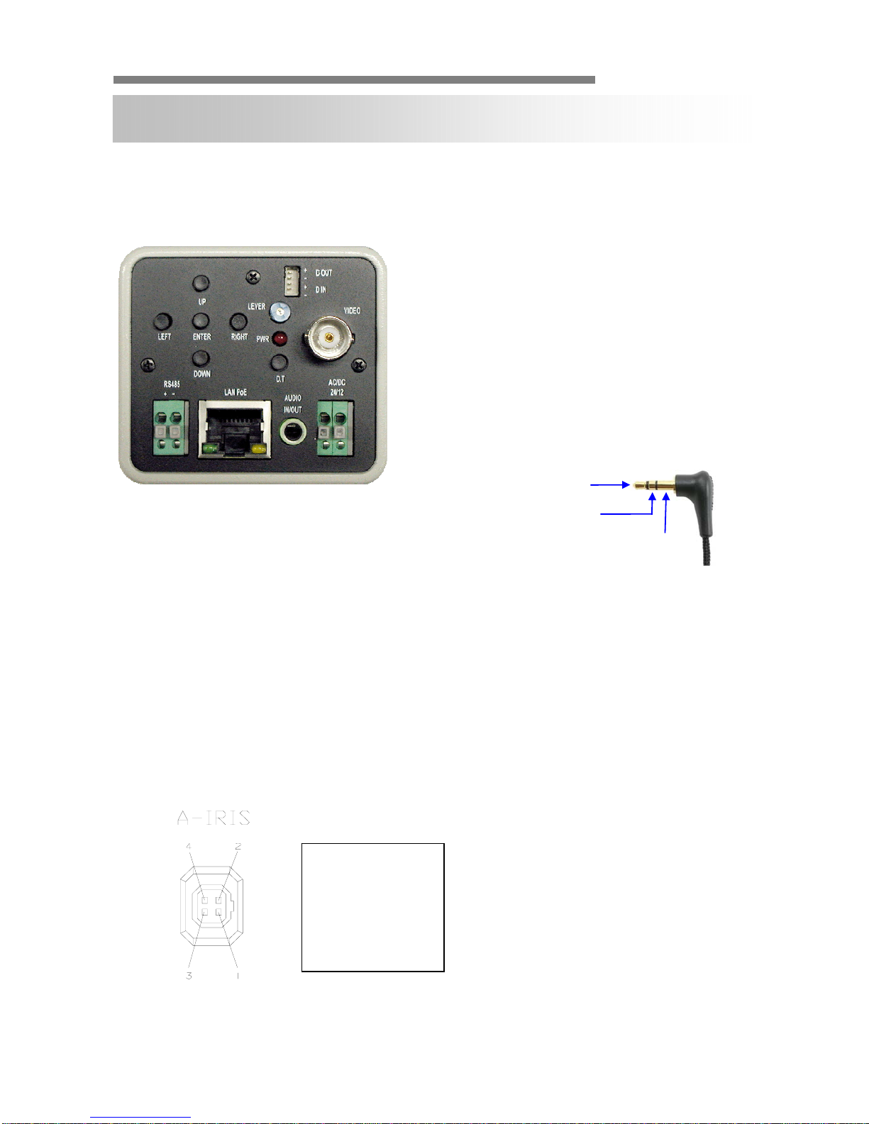
▲CONNECTION
▲ LENS SOCKET CONNECTION
INSTALLATION
1. OSD Control Button
2. DC Level Controller
3. DIO (Digital Input/Output)
4. 2nd Video Out (BNC connector)
5. Reset (factory Default Switch)
6. RS485 - Pan/Tilt Control
7. LAN/PoE - 10/100 Base-T LAN & PoE Support
8. Audio IN/OUT (Ø3.5 stereo jack)
- L : Audio IN (Mono)
- R : Audio OUT (Mono)
9. Power : DC12V 1A, AC24V 0.6A (Dual Power)
GND
CAUION :
Check for polarity when using a POE(Power of Ethernet) power supply.
- Su
pp
ort: IEEE 802.3a
f
DC Driven (DC)
1. control –
2. control +
3. drive +
4. GND

INSTRUCTION MANUAL
CamPilotMR100 7/52
▲Adjustment of Back Focus
This adjustment should only be carried out, if the lens cannot be focused
properly through the entire picture using the lens focus ring. In this case please
proceed as follows:
1. Attach the lens onto the camera front.
2. Adjust the focus by using focus lever up and down.
3. Tighten the locking screw not to change the focus from external impact.
▲Adjustment of DC lens
To adjust a lens with automatic iris (DC driven or video driven) to the camera,
please proceed as follows:
1. Turn the Level potentiometer (position: AI lenses at the lens itself, DC lenses:
at the camera) to the max. position H (turn right). The monitor picture then
appears to be too bright.
2. Slowly turn the Level potentiometer back until the monitor picture appears to
be perfect and is not too bright anymore. Then turn the potentiometer back to
the right (in direction ”H”) just a little bit.
3. Check the lens performance by using the camera under different and/or
changing light conditions.

INSTRUCTION MANUAL
CamPilotMR100 8/52
▲Focusing the Camera Lens
After you have selected the correct picture detail you have to adjust the lens
focus. The focus adjustment needs to be done with the iris fully open, since the
camera has the smallest depth of focus in this position. If the focus adjustment
was not done with the iris completely open, the picture would appear to be
sharp during the day but slowly getting out of focus the more the light
disappears. To fully open the lens, use a grey filter in front of the lens,
provided you are using a lens with automatic iris. Adjust the focus while the iris
is fully open using the lens focus ring. Make sure the most important picture
details are in optimum focus (use a service monitor). If it is not possible to bring
the picture into focus, please adjust the back focus of the camera as described
above.
If you intend to use I.R. illumination at a later stage, you must use an I.R. pass
filter together with the grey filter during focus adjustment to ensure that only I.R.
light will get through to the camera chip and the focus adjustment is done
according to this spectrum, only. Attention: I.R. light can only be used in
combination with mono cameras, not color cameras!

INSTRUCTION MANUAL
CamPilotMR100 9/52
▲OSD MENU SETTINGS
LENS MASK 1
E. SHUTTER MASK 2
BLC MASK 3
MAX_DR MASK 4
AGC MASK 5
STARLIGHT MASK 6
WB MODE SYNC MODE
R-Y GAIN V_PHASE
B-Y GAIN
D&N MODE CAMERA ID
C-SUP TITLE
A-SUP DPC
MONITOR
LANGUAGE
BAUDRATE
OMNI LENS
MIRROR EXIT
SHARPNESS SAVE & EXIT
GAMMA FACTORY SET
FREEZE
NEGA
3D_DNR
D_ZOOM
SLC
HME
DIS
MOTION
SET WINDOW
ALL SET
ALL CLEAR
SENSITI
SHOW INDI
DELAY OUT
1. EXPOSURE 6. PRIVACY
2. COLOR 7. SYNC
5. MOTION
3. DAY&NIGHT 8. SETUP
4. FUNCTION 9. EXIT

INSTRUCTION MANUAL
CamPilotMR100 10/52
▲INSTALLATION PROCESS
1) Connecting power supply, LAN and audio cables to a CamPilot MR100.
•DC 12V - Power (Adapter , DC 12V/1000mA)
•ETHERNET - LAN cable (RJ45 Jack)
- A client PC or a network devices is connected to the CamPilot MR100.
•AUDIO - Audio IN/OUT
cable
- IN : Input from a microphone (RCA)
- OUT : Output to a speaker (RCA)
※ Network Configuration Example
NETWORK CONFIGURATION
Hub
Local Monitoring
Router
Router
DDNS Server
CamPilot
MR100
Hub
Router
Monitor
/ DVR
/
Matrix
IP Decoder
Center Monitoring
Network
Este manual sirve para los siguientes modelos
1
Tabla de contenidos


