CAME CBX series Manual de usuario

#!-%
CBX
AUTOMATION FOR INDUSTRIAL AND
RESIDENTIAL ENTRANCES
INSTALLATION MANUAL

All the data and information contained herein is considered subject to change at any time and at our discretion
2
ENGLISH
2.1 Destination
1 Legend
This symbol indicates sections to be read with particular care.
This symbol indicates sections concernig safety
This symbol indicates notes to communicate to users.
4.1 Gearmotor
AllgearmotorsaredesignedandbuiltbyCAMECANCELLIAUTOMATICIS.p.A.incompliancewiththeprevailingsafetyregulations.
Guaranteed for 24 months unless tampered with.
The enclosure is made up of a part in aluminium alloy inside of which the non-reversible, electromechanical gearmotor operates,
and partly in ABS plastic that houses the terminals for the electrical wiring.
The CBX series has several versions depending on the type of use - residential, condominium or industrial - with mechanical end
stop or with an encoder system (see para. 2.3 Fields of use).
The complete line:
Gearmotor 230V A.C. with encoder and control boards
001C-BXE Gearmotor 230V A.C. with encoder
002 ZCX10 - Control board
002 ZCX10C - Control board with safety block and command buttons
Gearmotor 24V A.C. with encoder and control boards
001C-BXE Gearmotor 24V A.C. with encoder
002 ZL80 -Control board
002 ZCX80C - Control board with safety block and command buttons
002 BN1 - Board for connecting 2 emergency batteries (12V - 1.2Ah)
The following standard were complied with for this product: EN 12978, UNI EN 954-1, CEI EN 60335-1, UNI EN 12453.
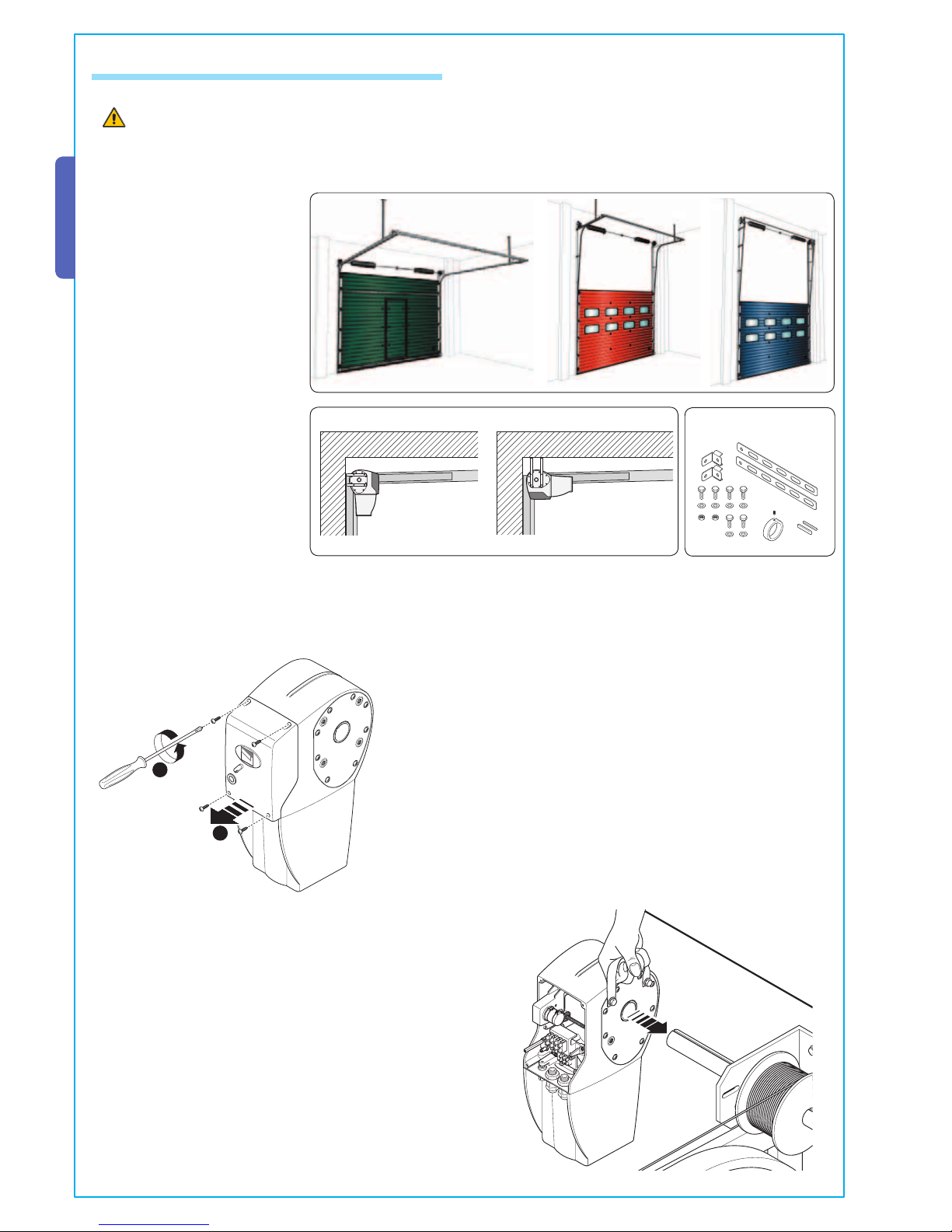
2 Destination and use applications
The CBX series gearmotor was designed to automate chiefly sectional doors with direct transmission on the shaft using springs
or with chain drive; however, the CBX can also be used for sliding and folding doors with the respective accessories.
Uses other than the ones described above and installations using methods other than those shown in this technical
manual are considered prohibited.
3 Standard followed
4 Description
2.2 Use applications
For sectional doors with direct transmission: door height up to 5.5 m;
Speed* 7.15 m/1’ with cable winder drum ~Ø 105 mm;
Speed* 9.3 m/1’ with cable winder drum ~Ø 138 mm.
For sectional doors with chain drive: door height up to 8.5 m;
Speed* 9.15 m/1’ with cable winder drum ~Ø 208 mm.
For sliding and folding doors: door width up to 5.5 m for C-BXE / C-BXE24 / C-BXET;
door width up to 11 m for C-BX / C-BXT.
wing weight 1000 kg max.
* The speed varies depending on the diameter of the drum; in particular, models of cable winder drums used by the main sectional
door manufacturers in the specific dimensions were inserted into the descriptions.
2.3 Fields of use
C-BX / C-BXE Residential - Condominium - Industrial
C-BXE24 Residential - Condominium
C-BXT / C-BXET Industrial
“IMPORTANT SAFETY INSTRUCTIONS FOR INSTALLATION”
“CAUTION: IMPROPER INSTALLATION MAY CAUSE SERIOUS DAMAGE, FOLLOW ALL INSTALLATION INSTRUCTIONS CAREFULLY”
“THIS MANUAL IS ONLY FOR PROFESSIONAL INSTALLERS OR QUALIFIED PERSONS”

3
All the data and information contained herein is considered subject to change at any time and at our discretion
ENGLISH
#!-%
4.2 Parts description
1 - Gearmotor
2 - Release handle
3 - Lower cap
4 - Protection cover
GEARMOTOR UNIT
ACCESSORIES
1 - C001 - Winch for manually moving sectional doors
2 - C002 - Pendulum release system
3 - C003 - Chain tightener transmission system and brackets
for sliding doors
4 - C004 - Chain tightener transmission system and brackets
for folding doors
5 - C005 - Chain drive system for sectional doors
6 - C006 - Package of two brackets for sectional doors
7 - C007/8 - Adapter for sectional doors
8 - CMS - Release handle with personalized key
9 - CGP - Chain guide with protective guard
10 - CCT - Simple 1/2” chain
11 - CGIU - Coupling for 1/2” chain
3
41
2
1
29
3
4
5
6
11
#!-%
2
8
10
7
Gearmotor 230V / 400V three-phase with encoder and control boards
001C-BXET - Gearmotor 230V/400V A.C. with encoder
002 ZT5 - Control board
002 ZT5C - Control board with safety block and command buttons
Gearmotor 230V A.C. with mechanical end-stop and control boards
001C-BX - Gearmotor 230V A.C. with mechanical end-stop
002 ZC3 - Control board
002 ZC3C - Control board with safety block and command buttons
Containers and electrical cards for gearmotors 230V
001S4339 - Container
001S4339C – Container with safety release and command buttons
001S4340 - Container
001S4340C – Container with safety release and command buttons
003 ZC5 - Basic electrical card
003 ZM2 - Multi-function electrical card
Gearmotor 230/400V three-phase with mechanical end-stop and control boards
001C-BXT - Gearmotor 230V/400V A.C. three phase with mechanical end-stop
002 ZT6 - Control board
002 ZT6C - Control board with safety block and command buttons
The CBX series comes with the following complementary accessories:
001 CMS - Release handle with personalized key and return cord (7 m long);
001 CGP - Chain guide with protective guard for industrial doors;
009 CCT - Simple 1/2” chain for sliding or folding doors;
009 CGIU - Coupling for 1/2” chain;
001 C001 - Winch for manually moving sectional doors;
001 C002 - Pendulum release system;
001 C003 - Chain tightener transmission system and brackets for sliding doors;
001 C004 - Chain tightener transmission system and brackets for folding doors;
001 C005 - Chain drive system for sectional doors with heights over 5.5 m;
001 C006 - Package of two brackets for sectional doors (specific for direct transmission applications);
001 C007/8 - Adapter for sectional doors con Ø 25 mm post (C007) or Ø 40 mm post (C008);
Important! Make sure that the control and safety equipment and accessories are CAME original. Only CAME products are gua-
ranteed to make the system easy to use and maintain.

All the data and information contained herein is considered subject to change at any time and at our discretion
4
ENGLISH
5.1 Preliminary checks
Before proceeding with the installation, it is necessary to:
•Thegearmotor mustbe installed in an area protected from shocks;the anchoring surface mustbe solid; andappropriate parts
(screws, plugs, etc) must be used to anchor the gearmotor to the surface;
• Provide for suitable omnipolar disconnection device with more than 3 mm between contacts to section power supply.
• Connections inside the case made for protection circuit continuity are allowed as long as they include additional insulation
with respect to other internal drive parts.
• Install suitable tubes and ducts for electric cable passage to guarantee protection against mechanical damage.
• The structure of the door must be sufficiently sturdy, the hinges must be efficient and there must be no friction between fixed
or mobile parts;
• Check the presence of a mechanical end-stop during opening and closing.
Installation must be carried out by expert qualified personnel and in full observance of regulations in force.
5 Installation
SECTIONAL DOORS SLIDING DOORS FOLDING DOORS
4.4 Size measurements
Measurements in mm
4.3 Technical information
C-BX / C-BXE GEARMOTOR
Power supply panel: 230V A.C. 50/60Hz
Motor power supply: 230V A.C. 50/60Hz
Absorption*: 3A
Rated power*: 450W
Max. torque*: 60 Nm
Reduction ratio: 1/67.45
Drive shaft revolutions: 34(CBX)/20.5(CBXE)
Motor revolution speed: 21.5 rpm
Operative intermittence: 30%
Protection level: IP54
Weight: 15 kg
Working time:#
#
C-BXE24 GEARMOTOR
Power supply panel: 230V A.C. 50/60Hz
Motor power supply: 24V D.C.
Absorption*: 9A max.
Rated power*: 240W
Max. torque*: 25 Nm
Reduction ratio: 1/67,45
Drive shaft revolutions: 20,5
Motor revolution speed: 26,5 rpm
Operativeintermittence:intensive service
Protection level: IP54
Weight: 15 kg
Working time:
C-BXT / C-BXET GEARMOTOR
Power supply panel: 230-400V A.C. - 50/60Hz
Motor power supply: 230-400V A.C.-50/60Hz
Absorption*: 2,5A
Rated power*: 780W
Max. torque*: 80 Nm
Reduction ratio: 1/67,45
Drive shaft revolutions: 34(CBXT)/20,5(CBXET)
Motor revolution speed: 21,5 rpm
Operative intermittence: intensive service
Protection level: IP54
Weight: 15 kg
Working time:
#
#
#
#
* Values relating to the designated electrical board
#!-%
2

5
All the data and information contained herein is considered subject to change at any time and at our discretion
ENGLISH
5.3 Cable list and minimun thickness
Connections Type of cable Length of cable 1 < 10 m Lengthcable10<20m Length cable 20 < 30 m
230/400V 3F power supply
FROR CEI
20-22
CEI EN
50267-2-1
4G x 1,5 mm24G x 2,5 mm24G x 4 mm2
230V 2F power supply 3G x 1,5 mm23G x 2,5 mm23G x 4 mm2
230/400V 2F/3Fpowersupplymotor 4G x 1,5 mm24G x 1,5 mm24G x 1,5 mm2
24V power supply motor 2 x 1 mm22 x 1,5 mm22 x 2,5 mm2
24V - 230V flashing lamp 2 x 0,5 mm22 x 1 mm22 x 1,5 mm2
Photoelectric TX 2 x 0,5 mm22 x 0.5 mm22 x 0,5 mm2
Photoelectric RX 4 x 0,5 mm24 x 0,5 mm24 x 0,5 mm2
24V power supply accessory 2 x 0,5 mm22 x 0,5 mm22 x 1 mm2
Control button 2 x 0,5 mm22 x 0,5 mm22 x 0,5 mm2
End stop 3 x 0,5 mm23 x 1 mm23 x 1,5 mm2
Encoder connection 2402C 22AWG max. 30 m
Antenna connection RG58 max. 50 m
N.B.: An evaluation of the size of the cables with lengths other than the data in the table must be made based on the effective ab-
sorption of the connected devices, according to the instructions indicated by the CEI EN 60204-1 standards.
For connections that require several loads on the same line (sequential), the size given on the table must be re-evaluated based on
actual absorption and distances.
28
48 48
28
1 - Gearmotor
2 - Control panel with push-buttons
3 - Radio receiver
4 - Flaching light indicating movement
5 - Antenna
6 - Safety photocells
7 - Gearmotor release
5.2 Tools and materials
Make sure all tools and materials necessary are within reach to install the edge in maximum safety, according to regulations in
force. The following figure illustrates the minimum equipment for the installer.

All the data and information contained herein is considered subject to change at any time and at our discretion
6
ENGLISH
5.4 Installing the automation on sectional doors
The following applications are only examples, as the space for installing the ratiomotor and accessories varies accord-
ing to obstructions. It is thus up to the system installer to select the most suitable solution.
C006
Fig.2
VERTICAL APPLICATION HORIZONTAL APPLICATION
CAME
1
2
Fig.1
DIRECT TRANSMISSION - The
CBX ratiomotor is supplied
ready for installation with a
direct action on the door springs
shaft, with a shaft diameter of 1
inch (fig. 1); for special volume
requirements, it is also possible
to install it horizontally (fig. 2)
but for both cases use accessory
(Art. C006).
1) Before securing the ratiomotor, open the protection cover to facilitate
post-assembly operations.
2) Insert the ratiomotor on the spring pole using the handle on the
ratiomotor.

7
All the data and information contained herein is considered subject to change at any time and at our discretion
ENGLISH
#!-%
2
1
2
3
1
2
A
B
Fig.3
3) Manually release the ratiomotor by turning the rod clockwise
and move the door to make the pole cavity coincide with that of the
ratiomotor’s cable shaft.
4) Insert tongue A or B depending on the
type of shaft (see fig. 3) between the two
cavities, insert the bushing on the pole and
secure with the grub screw.
5) Assemble the brackets (Art. C006) and secure them (avoid-
ing blocking them) to the ratiomotor with the supplied screws.
6) Secure the brackets on the wall with suitable screws chosen
according to the shape of the wall to secure the brackets onto
the ratiomotor.
SOLID SHAFT
HOLLOW SHAFT

All the data and information contained herein is considered subject to change at any time and at our discretion
8
ENGLISH
CHAIN TRANSMISSION
- Installations on sectional
doors higher than 5.5 m, for
this type of application you
must use the accessory (Art.
C005).
H > 5.5 m.
CAME
1
2
4) Secure the fixing bracket to the ratiomotor with the supplied screws.
1
2
1) Before securing the ratiomotor, open the protection cover to facilitate
post-assembly operations.
2) Insert tongue A or B (see fig.1) into the cavity
of the sprung pole, then insert toothed crown Z40
onto the pole opposite the tongue and secure it
with the grub screw.
3) Insert tongue A into the cavity of the pinion toothed sprocket shaft Z26, insert the
pinion, into the motor cable shaft and secure it with a screw UNI 5933 M6x16 and washer
from the opposite side.
A
B
Fig.1
C005
SOLID SHAFT
HOLLOW SHAFT

9
All the data and information contained herein is considered subject to change at any time and at our discretion
ENGLISH
8) Then secure
the ratiomotor’s
fixing bracket with
appropriate screws
chosen according to
the shape on the wall,
being sure that the two
toothed crowns are
perpendicular to each
other.
1
1
1
3
2
5) Unite the two ends of the chain with the coupling and
insert it onto the toothed crown Z40 leaving it hanging.
6) Anchor the ratiomotor’s shaft pinion to the hanging chain.
7) Release the ratiomotor by hand by turning the rod clockwise.

All the data and information contained herein is considered subject to change at any time and at our discretion
10
ENGLISH
5.5 Installing the automation on sliding doors
DOORS WITH ONE OR TWO WINGS - For
installations with sliding gates/doors having
one or two wings, you must use the acces-
sory C003 (transmission system for sliding
gates). ++
1) Before securing the ratiomotor, open the protection cover to facilitate
post-assembly operations.
1
2
3
2) Assemble the two fixing brackets and secure them to the ratiomotor.
3) Insert the tongue into the cavity of the toothed pinion’s shaft Z26,
insert the pinion into the motor cable shaft and secure it with a screw
(UNI 5933 M6x16) and washer from the opposite side.
4) Secure the assembly above to the right or left of the door
using suitable items chosen according to the wall’s shape.
C003 CCT CGIU
CAME
1
2
Otros manuales para CBX series
1
Este manual sirve para los siguientes modelos
5
Tabla de contenidos
Otros manuales de Motor de CAME


