CADnetwork RenderCube XL Manual de usuario

RenderCube XL
1-1
Product Introduction
Chapter 1: Product Introduction
• Unplugthepowercordfromthewallsocketbeforetouchinganycomponent.
• Beforehandlingcomponents,useagroundedwriststraportouchasafelygrounded
objectorametalobject,suchasthepowersupplycase,toavoiddamagingthemdue
tostaticelectricity.
• HoldcomponentsbytheedgestoavoidtouchingtheICsonthem.
• Wheneveryouuninstallanycomponent,placeitonagroundedantistaticpadorinthe
bagthatcamewiththecomponent.
• Beforeyouinstallorremoveanycomponent,ensurethattheATXpowersupplyis
switchedofforthepowercordisdetachedfromthepowersupply.Failuretodoso
maycauseseveredamagetothemotherboard,peripherals,orcomponents.
1.1 Motherboard overview
1.1.1 Before you proceed
Takenoteofthefollowingprecautionsbeforeyouinstallmotherboardcomponentsorchange
anymotherboardsettings.

1-2 Chapter 1: Product Introduction
Referto1.1.9 Internal connectorsand2.3.1 Rear I/O connectionformoreinformation
aboutrearpanelconnectorsandinternalconnectors.
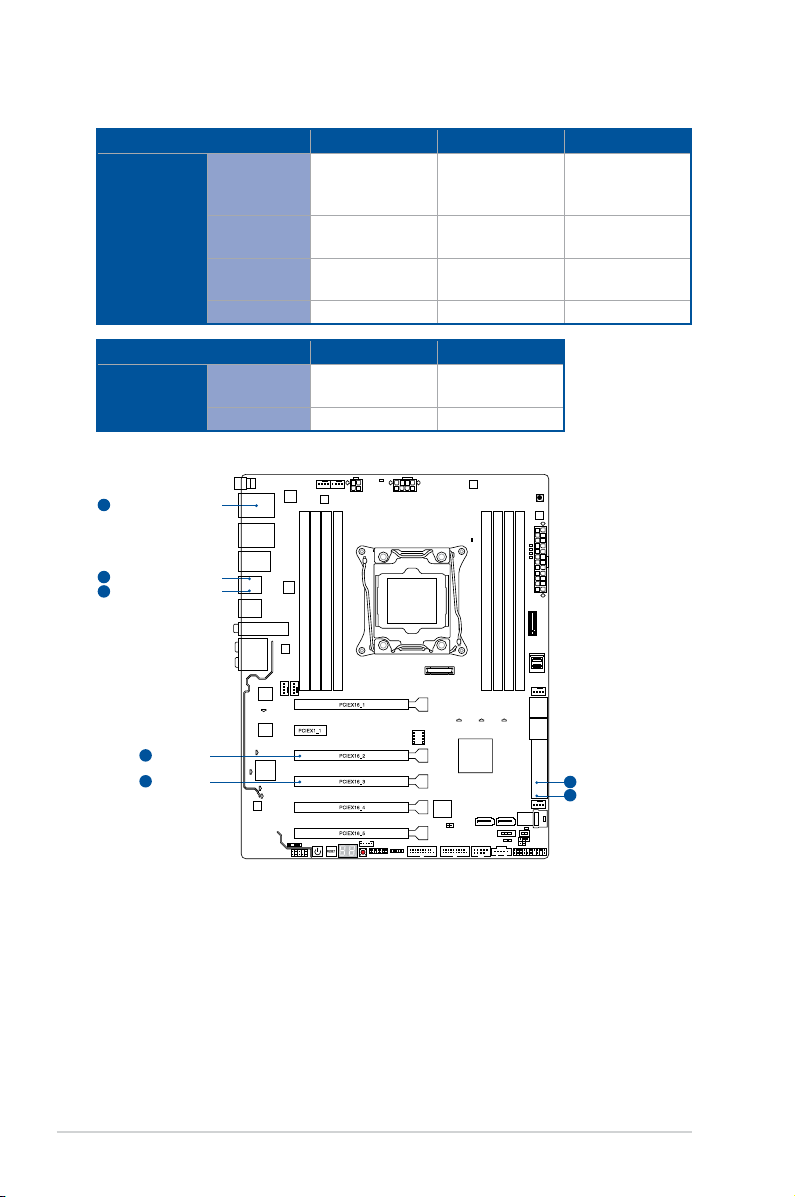
1.1.2 Motherboard layout

ReRenderCube XL
1-3
Layout contents
Connectors/Jumpers/Buttons and switches/Slots Page
1. DDR4DIMMslots 1-5
2. CPU,CPUoptional,waterpump,highamp,extension,andchassisfan
connectors(4-pinCPU_FAN;4-pinCPU_OPT;4-pinW_PUMP;4-pin
H_AMP_FAN;5-pinEXT_FAN;4-pinCHA_FAN1-2)
1-26
3. ATXpowerconnectors(24-pinEATXPWR;8-pinEATX12V_1;4-pin
EATX12V_2)
1-27
4. LGA2011-v3CPUsocket 1-4
5. MemOK!button 1-12
6. M.2Socket3 1-30
7. U.2connector(U.2_1-2) 1-24
8. Intel®SerialATA6Gb/sconnectors(7-pinSATA6G_12,SATA6G_34,
SATA6G_56/SATAEXPRESS_1,SATA6G_78,SATA6G_910)
1-21
9. EZXMPswitch 1-14
10. CPUOverVoltagejumper(3-pinCPU_OV) 1-14
11. DirectKeyconnector(2-pinDRCT) 1-29
12. Systempanelconnector(20-3pinPANEL) 1-28
13. Thunderboltheader(5-pinTB_HEADER) 1-30
14. USB2.0connectors(10-1pinUSB1112) 1-25
15. SLI/CFXswitch 1-13
16. USB3.0connectors(20-1pinUSB3_12,USB3_34) 1-23
17. T_Sensorconnector(2-pinT_SENSOR1) 1-32
18. RGBHeader(4-pinRGB_HEADER) 1-31
19. TPMconnector(14-1pinTPM) 1-29
20. ClearCMOSbutton(CLR_CMOS) 1-13
21. Q-CodeLEDs 1-17
22. Resetbutton 1-11
23. Power-onbutton 1-11
24. Frontpanelaudioconnector(10-1pinAAFP) 1-22
25. Digitalaudioconnector(4-1pinSPDIF_OUT) 1-22

1-4 Chapter 1: Product Introduction
1.1.3 Central Processing Unit (CPU)
ThemotherboardcomeswithasurfacemountLGA2011-v3socketdesignedforIntel®Core™
i7processors.
• EnsurethatallpowercablesareunpluggedbeforeinstallingtheCPU.
• Uponpurchaseofthemotherboard,ensurethatthePnPcapisonthesocketandthe
socketcontactsarenotbent.ContactyourretailerimmediatelyifthePnPcap
ismissing,orifyouseeanydamagetothePnPcap/socketcontacts/motherboard
components.willshoulderthecostofrepaironlyifthedamageisshipment/transit-
related.
• Keepthecapafterinstallingthemotherboard.willprocessReturnMerchandise
Authorization(RMA)requestsonlyifthemotherboardcomeswiththecaponthe
LGA2011-v3socket.
• Theproductwarrantydoesnotcoverdamagetothesocketcontactsresultingfrom
incorrectCPUinstallation/removal,ormisplacement/loss/incorrectremovalofthePnP
cap.

ReRenderCube XL
1-5
Recommended memory configurations
1.1.4 System memory
ThemotherboardcomeswitheightDDR4(DoubleDataRate4)QuadInlineMemory
Modules(DIMM)slots.
ADDR4moduleisnotcheddifferentlyfromaDDR,DDR2,orDDR3module.DONOT
installaDDR,DDR2,orDDR3memorymoduletotheDDR4slot.

1-6 Chapter 1: Product Introduction
• YoumayinstallvaryingmemorysizesinChannelA,ChannelB,ChannelC,and
ChannelD.Thesystemmapsthetotalsizeofthelower-sizedchannelforthequad-
channelconguration.Anyexcessmemoryfromthehigher-sizedchannelisthen
mappedforsingle-channeloperation.
• AccordingtoIntel®CPUspec,DIMMvoltagebelow1.65Visrecommendedtoprotect
theCPU.
• Duetothememoryaddresslimitationon32-bitWindows®OS,whenyouinstall4GB
ormorememoryonthemotherboard,theactualusablememoryfortheOScanbe
about3GBorless.Foreffectiveuseofmemory,werecommendthatyoudoanyofthe
following:
a) Useamaximumof3GBsystemmemoryifyouareusinga32-bitWindows®OS.
b) Installa64-bitWindows®OSwhenyouwanttoinstall4GBormoreonthe
motherboard.
c) Formoredetails,refertotheMicrosoft®supportsiteathttp://support.microsoft.
com/kb/929605/en-us.
• ThedesignoftheDIMMfanmayvary.EnsurethattheDIMMfantstothe
motherboard
• ThedefaultmemoryoperationfrequencyisdependentonitsSerialPresenceDetect
(SPD),whichisthestandardwayofaccessinginformationfromamemorymodule.
Underthedefaultstate,somememorymodulesforoverclockingmayoperateata
lowerfrequencythanthevendor-markedvalue.Tooperateatthevendor-marked
oratahigherfrequency,refertosection3.5 Ai Tweakermenu formanualmemory
frequencyadjustment.
• Forsystemstability,useamoreefficientmemorycoolingsystemtosupportafull
memoryload(8DIMMs)oroverclockingcondition.
• Memorymoduleswithmemoryfrequencyhigherthan2133MHzandtheir
correspondingtimingortheloadedXMPprofileisnottheJEDECmemorystandard.
ThestabilityandcompatibilityofthememorymodulesdependontheCPU’s
capabilitiesandotherinstalleddevices.
• AlwaysinstalltheDIMMSwiththesameCASLatency.Foranoptimumcompatibility,
werecommendthatyouinstallmemorymodulesofthesameversionordatacode
(D/C)fromthesamevendor.Checkwiththevendortogetthecorrectmemory
modules.
• exclusivelyprovideshyperDIMMsupportfunction.
• HyperDIMMsupportissubjecttothephysicalcharacteristicsofindividualCPUs.Load
theX.M.P.orD.O.C.P.settingsintheBIOSforthehyperDIMMsupport.
• VisitthewebsiteforthelatestQVL.
Memory configurations
Youmayinstall1GB,2GB,4GB,8GBand16GBunbufferedandnon-ECCDDR4DIMMs
intotheDIMMsockets.

ReRenderCube XL
1-7
1.1.5 Expansion slots
Unplugthepowercordbeforeaddingorremovingexpansioncards.Failuretodosomay
causeyouphysicalinjuryanddamagemotherboardcomponents.
Slot No. Slot Description
40-LANE 28-LANE
1PCIe3.0/2.0x16_1slot PCIe3.0/2.0x16_1slot
2PCIe2.0x1_1slot PCIe2.0x1_1slot
3PCIe2.0x16_2slot PCIe2.0x16_2slot
4PCIe3.0/2.0x16_3slot PCIe3.0/2.0x16_3slot
5PCIe3.0/2.0x16_4slot PCIe3.0/2.0x16_4slot
6PCIe3.0/2.0x16_5slot PCIe2.0x16_5slot

1-8 Chapter 1: Product Introduction
• WerecommendthatyouprovidesufcientpowerwhenrunningCrossFireX™orSLI™
mode.
• ConnectachassisfantothemotherboardconnectorlabeledCHA_FAN1-2when
usingmultiplegraphicscardsforbetterthermalenvironment.
40-LANE CPU PCI Express 3.0 operating mode
VGA configuration PCIe 3.0/2.0
x16_1
PCIe 3.0/2.0
x16_3
PCIe 3.0/2.0
x16_4
PCIe 3.0/2.0
x16_5
SingleVGA/PCIecard
x16
(singleVGA
recommended)
N/A N/A N/A
DualVGA/PCIecards x16 x16 N/A N/A
TripleVGA/PCIecards x16 x16 N/A x8
x8 x8 x8 N/A
28-LANE CPU PCI Express 3.0 operating mode
VGA configuration PCIe 3.0/2.0 x16_1 PCIe 3.0/2.0 x16_3 PCIe 3.0/2.0 x16_4
SingleVGA/PCIecard x16(singleVGA
recommended) N/A N/A
DualVGA/PCIecards x16 x8 N/A
TripleVGA/PCIecards x8 x8 x8

ReRenderCube XL
1-9
40-LANE CPU Bandwidth allocation
USB3_34 USB3.1_EA34 SATA Express
PCIEX16_2
X2
not occupied
(default)
V V SATA
X2
occupied
V
(USB2.0speed) V SATA
X4 V
(USB2.0speed) -SATA
none V V SATA/PCIE
M.2 U.2_2
PCIEX16_3
X16
(default) - -
X8 V V
U.2_1
PCIEX16_5
X8
(default) -
X4 V
1-10 Chapter 1: Product Introduction
PCIEX16_2
1
shared with PCIEX16_2
1
shared with PCIEX16_3
2
PCIEX16_3
2
shared with PCIEX16_2
1
shared with PCIEX16_2
1
shared with PCIEX16_3
2
28-LANE CPU Bandwidth allocation
USB3_34 USB3.1_EA34 SATA Express
PCIEX16_2
X2
not occupied
(default)
V V SATA
X2
occupied
V
(USB2.0speed) V SATA
X4 V
(USB2.0speed) -SATA
none V V SATA/PCIE
USB3.1_EA34 SATA Express
PCIEX16_3
X8
(default) - -
none V V
Tabla de contenidos
Otros manuales de Placa madre de CADnetwork


Manuales populares de Placa madre de otras marcas


Telit Wireless Solutions
Telit Wireless Solutions SL869-3DR Manual de usuario

Gigabyte
Gigabyte GA-9IVDT Manual de usuario

Texas Instruments
Texas Instruments ADS8372EVM Manual de usuario

Commell
Commell MS-C73 Manual de usuario

IBT Technologies
IBT Technologies MB860 Manual de usuario

Nvidia
Nvidia TEGRA DG-04927-001_V01 Manual de usuario


