Buhler BCM-W Manual del propietario

Fluidcontrol
Installation and Operation Instructions
Original instructions
Oil Moisture Sensor
BCM-W
BE150101
12/2021
Bühler Technologies GmbH, Harkortstr. 29, D-40880 Ratingen
Tel. +49 (0) 21 02 / 49 89-0, Fax: +49 (0) 21 02 / 49 89-20
E-Mail: [email protected]
Internet: www.buehler-technologies.com

Bühler Technologies GmbH, Harkortstr. 29, D-40880 Ratingen
Tel. +49 (0) 21 02 / 49 89-0, Fax: +49 (0) 21 02 / 49 89-20
Internet: www.buehler-technologies.com
E-Mail: [email protected]
Read this instruction carefully prior to installation and/or use. Pay at-
tention particularly to all advises and safety instructions to prevent in-
juries. Bühler Technologies can not be held responsible for misusing
the product or unreliable function due to unauthorised modifications.
All rights reserved. Bühler Technologies GmbH 2023
Document information
Document No............................................................BE150101
Version.......................................................................... 12/2021

BCM-W
Contents
1 Introduction.....................................................................................................................................................................................................................2
1.1 Intended Use.........................................................................................................................................................................................................2
1.2 Functionality.........................................................................................................................................................................................................2
1.2.1 Humidity monitoring.......................................................................................................................................................................... 2
1.2.2 Temperature monitor.........................................................................................................................................................................2
1.2.3 IO-Link......................................................................................................................................................................................................2
1.3 Design types..........................................................................................................................................................................................................3
1.4 Model key...............................................................................................................................................................................................................3
1.5 Scope of Delivery.................................................................................................................................................................................................. 3
2 Safety instructions .........................................................................................................................................................................................................4
2.1 Important advice .................................................................................................................................................................................................4
2.2 General hazard warnings ................................................................................................................................................................................. 5
3 Transport and storage ..................................................................................................................................................................................................6
4 Setup and connection ................................................................................................................................................................................................... 7
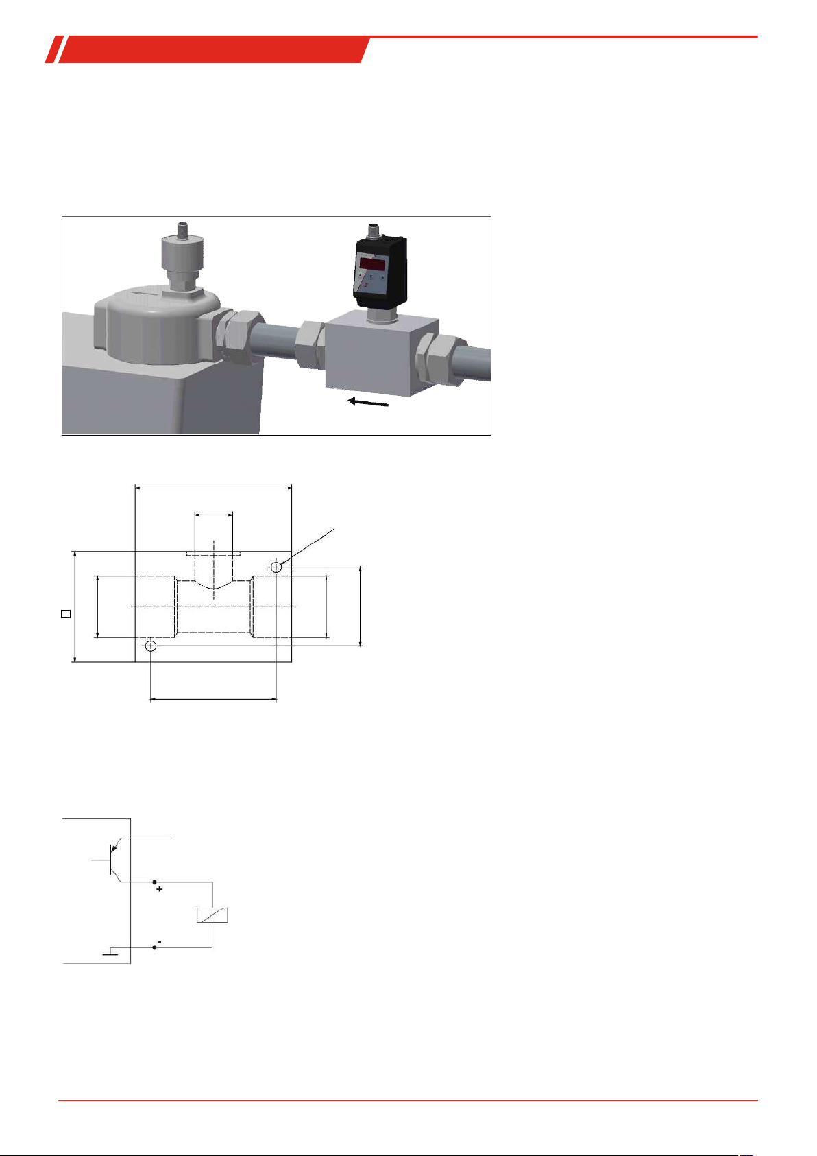
4.1 Installation ............................................................................................................................................................................................................ 7
4.1.1 Installation recommendation ..........................................................................................................................................................8
4.2 Electrical connections.........................................................................................................................................................................................8
5 Operation and Control..................................................................................................................................................................................................9
5.1 BCM-WD/BCM-WR..............................................................................................................................................................................................9
5.1.1 Start-up procedure ..............................................................................................................................................................................9
5.1.2 LED statuses ...........................................................................................................................................................................................9
5.1.3 General key functions .......................................................................................................................................................................10
5.1.4 Keylock enabled .................................................................................................................................................................................. 10
5.1.5 Menu overview ....................................................................................................................................................................................11
5.1.6 Changing basic settings ................................................................................................................................................................... 12
5.1.7 Switching outputs...............................................................................................................................................................................15
5.1.8 Analogue outputs ............................................................................................................................................................................. 20
5.1.9 Diagnostic options.............................................................................................................................................................................22
5.2 BCM-WS................................................................................................................................................................................................................25
5.2.1 Start-up procedure ............................................................................................................................................................................25
5.2.2 Parameter configuration.................................................................................................................................................................25
5.2.3 Factory setting.....................................................................................................................................................................................25
5.2.4 Switching outputs..............................................................................................................................................................................25
5.2.5 Analogue outputs ..............................................................................................................................................................................25
6 Cleaning and Maintenance.......................................................................................................................................................................................26
7 Service and repair.........................................................................................................................................................................................................27
7.1 Removal information .......................................................................................................................................................................................27
7.2 Troubleshooting ................................................................................................................................................................................................27
7.3 Spare parts and accessories ...........................................................................................................................................................................28
8 Disposal ...........................................................................................................................................................................................................................29
9 Appendices .................................................................................................................................................................................................................... 30
9.1 Technical Data BCM-WS ................................................................................................................................................................................. 30
9.2 Technical Data BCM-WR/BCM-WD ..............................................................................................................................................................32
9.3 Dimensions BCM-WS........................................................................................................................................................................................33
9.4 Outputs BCM-WS...............................................................................................................................................................................................34
9.5 Outputs BCM-WD/BCM-WR...........................................................................................................................................................................34
9.6 Pin assignment BCM-WS.................................................................................................................................................................................34
9.7 Pin assignment BCM-WR/WD ....................................................................................................................................................................... 35
9.8 Display ranges....................................................................................................................................................................................................35
9.9 Current settings.................................................................................................................................................................................................35
9.10 Menu Sequence Overview ..............................................................................................................................................................................36
10 Attached documents ...................................................................................................................................................................................................37
iBühler Technologies GmbHBE150101 ◦ 12/2021

BCM-W
1 Introduction
1.1 Intended Use
Oil moisture sensors are used to monitor the water content in oils and the temperature. Oil moisture sensors must not be used
in highly flammable or corrosive liquids.
Please note the technical data in the appendix for the specific intended use, existing material combinations, as well as temper-
ature limits.
WARNING
All device models are solely intended for industrial applications. They are not safety com-
ponents. The devices must not be used if failure or malfunction thereof jeopardises the
safety and health of persons.
Use in explosive areas is prohibited.
1.2 Functionality
The sensor determines the relative humidity in oil through water activity (aW). The relative humidity behaves similar to water
activity. Here we can also use the term saturation level of oil. The sensor features a measuring chamber where humid air on the
inside and humidity in the medium become balanced. This puts the sensor in relation to the maximum saturation. So it
provides a degree of the saturation of the oil. Furthermore, the temperature is determined to allow for correcting the values. The
water activity is specified as a factor from 0 to 1. When multiplied by 100% this provides the relative humidity or the saturation
in percent.
The critical limit for saturation depends on several parameters specific to the system. The main advantage, however, is the con-
tinuous monitoring of humidity and temperature. The operating company can therefore make their own determinations on
changes in his system and adjust system parameters where necessary.
1.2.1 Humidity monitoring
The sensor element for determining the humidity is located inside the medium, protected by a tube. The relative humidity can
be continuously output as analog signal or digital signal (IO-Link) or as a switch signal. The threshold is preset and can be con-
figured depending on the model. Depending on the version, there are several switching outputs combined with one analog out-
put (4 - 20mA). The display versions can show the relative humidity in the display and output it to the analog output. The
thresholds for the switching outputs can be freely configured. The sensor versions have the option for analogue output of the re-
lative humidity. The threshold for the switching point is preset and can only be factory configured or via the digital interface.
1.2.2 Temperature monitor
The temperature is monitored via temperature sensor (Pt100) inside the medium, protected by a tube. Depending on the ver-
sion, there are several switching outputs combined with one analog output (4 - 20mA) or digital output (IO-Link). The display
types can display the temperature and output it to the analog output. The sensor types have the option for analogue temperat-
ure output.
Please note the technical data in the appendix.
1.2.3 IO-Link
If the sensor has an IO-Link interface, the identification, process and diagnostics data can be accessed. The sensor parameters
such as switching points or switch-back points can be set during operation. This requires an IO-Link Master with configuration
tool.
When replacing the sensor all previously configured parameters can be transferred to the new sensor.
The sensor has an electronic technical manual, the so-called IODD file. The IODD file contains all information required for system
integration. The file can be downloaded from https://ioddfinder.io-link.com.
For more information please visit: www.io-link.com
2 Bühler Technologies GmbH BE150101 ◦ 12/2021

BCM-W
1.3 Design types
The BCM is available as three basic models:
Model Description
BCM-WS Sensor without display
BCM-WD Sensor with display (display built into the sensor)
BCM-WR Combination of sensor and display (display for external installation)
The BCM will have different switching and analogue outputs depending on the configuration. The outputs are freely program-
mable.
The sensor versions are available with digital interface. Here the sensor uses the standardised technology IO-Link, an efficient
point-to-point communication. It uses the previous, proven and tested connection technology. Compatibility with the previous
technology is guaranteed.
1.4 Model key
Model BCM-WS
W
BCM - W S 1 0 -
Humidity
Type designation
Outputs
1S2A 1x switching output / 2x analog
1D Version IO-Link
Sensor
BCM Moisture Sensor
S
Version
Process connection
6Flange (per DIN 24557/T2)
/
0G3/4
2G1/2
Length (only model WS160)
Model BCM-WD/BCM-WR
W Humidity
Type designation Outputs
2S2A
1D1S
4S2A
Display with built-in sensor
Remote display with external sensor
BCM Moisture Sensor
D
R
Version Process connection
G 3/4
0
BCM - W 1 0 0 -
2 x switching output / 2 x analogue
1 x switching output / IO-Link
4 x switching output / 2 x analogue
G 1/22
1.5 Scope of Delivery
– BCM Oil Moisture Sensor
– Product documentation
– Connection/mounting accessories (optional)
3Bühler Technologies GmbHBE150101 ◦ 12/2021

BCM-W
2 Safety instructions
2.1 Important advice
This device may only be used if:
– The product is being used under the conditions described in the operating- and system instructions, used according to the
nameplate and for applications for which it is intended. Any unauthorized modifications to the device will void the warranty
provided by Bühler Technologies GmbH,
– the specifications and markings in the type plate are observed,
– the limits in the data sheet and the instructions must be observed,
– monitoring equipment / protection devices must be connected correctly,
– the device is protected from mechanical damage and vibration,
– service and repairs not described in these instructions is performed by Bühler Technologies GmbH,
– using genuine replacement parts.
These operating instructions are a part of the equipment. The manufacturer reserves the right to change performance-, specific-
ation- or technical data without prior notice. Please keep these instructions for future reference.
Signal words for warnings
DANGER
Signal word for an imminent danger with high risk, resulting in severe injuries or death if not avoided.
WARNING
Signal word for a hazardous situation with medium risk, possibly resulting in severe injuries or death if not
avoided.
CAUTION
Signal word for a hazardous situation with low risk, resulting in damaged to the device or the property or
minor or medium injuries if not avoided.
NOTICE
Signal word for important information to the product.
Warning signs
These instructions use the following warning signs:
Warns of a general hazard Unplug from mains
Voltage warning Wear respiratory equipment
Warns not to inhale toxic gasses Wear a safety mask
Warns of corrosive liquids Wear gloves
General information
4 Bühler Technologies GmbH BE150101 ◦ 12/2021

BCM-W
2.2 General hazard warnings
The equipment must be installed by a professional familiar with the safety requirements and risks.
Be sure to observe the safety regulations and generally applicable rules of technology relevant for the installation site. Prevent
malfunctions and avoid personal injuries and property damage.
The operator of the system must ensure:
– Safety notices and operating instructions are available and observed,
– The respective national accident prevention regulations are observed,
– The permissible data and operational conditions are maintained,
– Safety guards are used and mandatory maintenance is performed,
– Legal regulations are observed during disposal,
– compliance with national installation regulations.
Maintenance, Repair
Please note during maintenance and repairs:
– Repairs to the unit must be performed by Bühler authorised personnel.
– Only perform conversion-, maintenance or installation work described in these operating and installation instructions.
– Always use genuine spare parts.
– Do not install damaged or defective spare part. If necessary, visually inspect prior to installation to determine any obvious
damage to the spare parts.
Always observe the applicable safety and operating regulations in the respective country of use when performing any type of
maintenance.
The method for cleaning the devices must be adapted to the IP protection class of the devices. Do not use cleaners which could
damage the device materials.
DANGER Toxic, acidic gases/liquids
Protect yourself from toxic, corrosive gasses/liquids when performing any type of work.
Wear appropriate protective equipment.
5Bühler Technologies GmbHBE150101 ◦ 12/2021

BCM-W
3 Transport and storage
Only transport the product inside the original packaging or a suitable alternative.
The equipment must be protected from moisture and heat when not in use. It must be stored in a covered, dry, dust-free room
at room temperature.
6 Bühler Technologies GmbH BE150101 ◦ 12/2021

BCM-W
4 Setup and connection
DANGER Electric voltage
Risk of electric shock
a) De-energise the system.
b) The equipment may only be installed, maintained and put into operation by instruc-
ted, competent personnel.
c) Always observe the applicable safety regulations for the operating site.
DANGER Toxic, acidic gases/liquids
Protect yourself from toxic, corrosive gasses/liquids when performing any type of work.
Wear appropriate protective equipment.
CAUTION Overpressure
Protect the device from static and dynamic overpressures.
Use suitable preventive measures!
4.1 Installation
Before installing the device, ensure the system is depressurised to prevent liquid from escaping. If necessary, use a collection
container.
The BCM comes fully assembled and can be installed in the piping flange connection on a tank housing using the screw-in
thread. When doing so, please ensure the sensor part is always fully bathed by medium to ensure the measured values dis-
played are correct. For built-in versions, use the flow cell, sold separately.
DANGER Electric voltage
Risk of electric shock
When connecting devices, please note the maximum voltages and currents (see tech-
nical data) and use the correct wire cross-sections and circuit breakers.
When selecting the connection lines, also note the maximum operating temperatures of
the devices.
The flange-mounted display units can be swivelled vertically by approx. 270° so they are easier to read. Please note the built-in
swivel stop. You will notice more resistance when reaching the stop. Turning it beyond this stop may damage the display unit.
7Bühler Technologies GmbHBE150101 ◦ 12/2021

BCM-W
4.1.1 Installation recommendation
Proper moisture sensor function requires the entire sensor element to be inside the medium at all times. The sensor version is
suitable for installation at the side of the tank. Here the installation position should be below the minimum liquid level. When
installing into a return pipe, be sure not to exceed the maximum flow rate.
With the BCM-WR version the remote display mounts to a top hat rail.
Installation example:
Assembly block dimensions:
100
G3/4
M8 - 15 deep
70
G1 1/4
80
G1 1/4
50
4.2 Electrical connections
Electricity is supplied via plug connectors. Please refer to the appendix for installation dimensions, nominal voltage and plug
configuration.
The switching outputs are PNP transistors (see illustration):
Supply voltage
Note: When measuring the switching output with high-load measuring device inputs or when used as a frequency output, the
load must be set to 10 kΩ between the output and earth (GND) to avoid faulty measurements.
8 Bühler Technologies GmbH BE150101 ◦ 12/2021
Este manual sirve para los siguientes modelos
3
Tabla de contenidos
Otros manuales de Sensor de seguridad de Buhler


