Broadata Communications 250E Series Manual de usuario

250E/260E Series
BROADCAST QUALITY
VIDEO/AUDIO/DATA
TRANSPORT SYSTEM
BCI reserves the right to make changes to the products described herein without
prior notice or consent. No liability is assumed as a result of their use or
application. All rights reserved.
©2001 Broadata Communications, Inc.

BCI250E/260E User’sManual
Broadcast Quality Video/Audio/Data Transport System
SAFETY INSTRUCTIONS AND
COMPLIANCE DECLARATIONS
PLEASEOBSERVETHEFOLLOWINGSAFETY
PRECAUTIONSASOURPRODUCTSCONTAIN
CLASS I LASER PRODUCTS
WARNING
Do not disconnect the fiber optic connector while the unit is powered
up. Exposure to laser radiation is possible when the laser fiber optic
connector is disconnected while the unit is powered up.
Although the fiber optic connectors in this product emit only Class 1
energythatis below the levels considered to behazardous,oneshould
neverstaredirectlyintoafiberopticconnectororanunconnectedfiber
end unless one can be certain that no exposure to laser energy could
occur.
CAUTION
This manual is intended for use by trained service personnel. The use
of controls, making adjustments, or performing operations other than
those specified may result in hazardous radiation exposure.
Thefollowinglabelorequivalentislocatedonthesurfaceoflaserproducts.
Thislabelindicatesthat the product is classified as a CLASS 1 LASER
PRODUCT.
SURGEPROTECTION DEVICERECOMMENDED
This product contains sensitive electrical components that may be
damaged by electrical spikes, surges, electric shock, lightning strikes,
etc. Use of surge protection systems is highly recommended in order
to protect and extend the life of your equipment.
CLASS 1 LASER PRODUCT

BCI250E/260E User’sManual
Broadcast Quality Video/Audio/Data Transport System
Broadata Technical Support, (800) 214-0222
4
TABLE OF CONTENTS
1.0 PRODUCT DESCRIPTION .............................................5
2.0 SETUP..............................................................................7
2.1 MOUNTING......................................................................8
2.2 CABLING AND CONNECTORS .....................................8
2.2.1 ELECTRICAL CABLE CONNECTION .........................8
2.2.1.1 VIDEO INTERFACE ...................................................8
2.2.1.2 AUDIO INTERFACE ...................................................9
2.2.1.3 SERIAL DATA INTERFACE .....................................11
2.2.2 OPTICAL FIBER CONNECTION...............................14
2.4 AC POWER CONNECTION ..........................................16
3.0 OPERATION...................................................................16
4.0 MAINTENANCE AND TROUBLESHOOTING..............17
4.1 MAINTENANCE .............................................................17
4.2 TROUBLESHOOTING ..................................................18
5.0 SPECIFICATIONS..........................................................20
6.0 SERVICE PROCEDURE ...............................................22
6.1 REPLACEMENT POLICY .............................................22
6.2 RETURN AND REPAIR SERVICE.................................22
7.0 LIMITED WARRANTY ....................................................23

BCI250E/260E User’sManual
Broadcast Quality Video/Audio/Data Transport System
1.0 PRODUCT DESCRIPTION
The BCI 250E/260E Series is a high performance unidirectional/
bi-directional transmission system capable of carrying simultaneous
broadcastqualityanalogvideo, audio,and/or datasignals. The standard
singlechannelmodels(250E/260E)willtransportonechannelofbroadcast
qualityanalog video,twoaudio channels,and/orone serialdata channel
(RS-232/RS-422)overmultimode or singlemode fiber. The 250E/260E
hasaloop-thoughvideomonitoringportintheTXunitandhastwooutput
video ports in the RX units. The video quality in the 250E/260E system
meets250Cshorthaulspecifications,whileitsaudiospecificationsexceed
professionalstandards.Manyversionsofopticaltransmittersandreceivers
canbe used inthe250E/260Eto address adifferentdistance coverage.
The 250E/260E features a digital fiber optic transmission technology,
capableofprovidingsharpervideoandcrispaudio,highfunctionalreliability,
and low operating cost with little or no maintenance. The quality of the
video,audioanddatatransmissionissuperiortotheanalogtransmission
systems(based onthecounterparts amplitudeor frequencymodulation)
schemes. Nouseradjustmentsare required in the 250E/260E system,
enablingfor a quick setupwithtrouble-free operation.
The 250E/260E comes in two packaging options: a rugged standalone
unit, or a plug-in card for a card cage system. Panel connectors are
providedforvideo(BNC),audio(terminalblock),anddata(terminalblock),
andfiberconnection(FC-typeforsinglemodefiberorST-typeformultimode
fiber). They are also easily monitored by separate LED indicators for
power, optical link,andchannel activity. SeeFigure1-1 for thefrontand
rearpanelsof a 250E.
Due to its digital transmission design, the 250E/260E is capable of
addressinga varietyofnon-standard configurations.

BCI250E/260E User’sManual
Broadcast Quality Video/Audio/Data Transport System
Broadata Technical Support, (800) 214-0222
6
Figure 1-1
250E Front/Rear Panels
BCI250E/260E User’sManual
Broadcast Quality Video/Audio/Data Transport System
2.0 SETUP
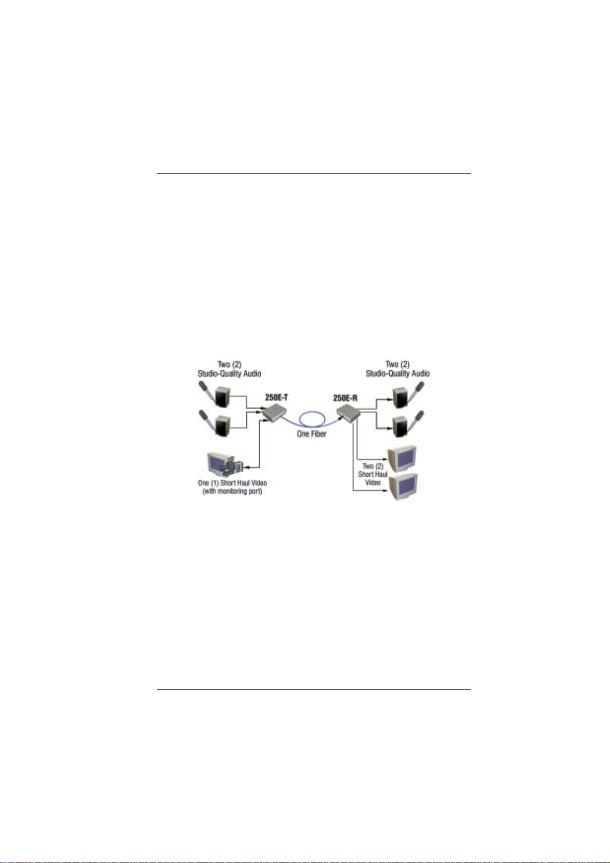
The BCI 250E/260E Series units are used in pairs. For unidirectional
applications, the 250E transmitter is located at the near-end, while a
250E receiver is connected at the far-end through one fiber. For
bi-directional applications, one 260E transceiver unit is located at the
near-endandconnectedthrough two optical fibers to an identical 260E
transceiverlocatedatthefar-endofthelink. Eachunitprovidesaseparate
electrical interface connector for the audio, video, and data signals.
Connections are one to one between both units. Figure 2-1 depicts a
typical installation.
Figure 2-1
250E Setup

BCI250E/260E User’sManual
Broadcast Quality Video/Audio/Data Transport System
Broadata Technical Support, (800) 214-0222
8
2.1 Mounting
Beforeinstallingtheunitsintoyourhousing, make sure there is
enoughspaceto pull andconnectboththe electrical andoptical
cables without stressing them beyond the manufacturer’s
limitations (also known as the bend radius minimum). Rack
Mountkitsareavailablethroughspecial order.
2.2 Cabling and Connectors
In order to setup the BCI 250E/260E properly, make sure to
observe the following instructions when installing the proper
cables. The250E/260E requires twopartsto thecablingsetup:
the electrical and the optical. For the optical part, observe the
following procedures, as there are various types of optical
connectorsas illustrated on the following page.
2.2.1 Electrical Cable Connection
Ontheelectricalside,itisrequiredthatthefollowingsteps
beobserved whenconnectingthevariousaudio, video,and
data terminal devices as they all require special attention,
andarethe only available electricalconnections. Theyare
described in the following steps.
2.2.1.1 Video Interface
The250E/260Eaccepts75-ohmvideosignalovercoaxial
cable terminated to a BNC connector (e.g., RG 59U
with a BNC connector). (See Figure 2-2). For analog
videoconnections,observe the following instructions.

BCI250E/260E User’sManual
Broadcast Quality Video/Audio/Data Transport System
Figure 2-2
Video Connection
1. Connectthe required videotransmissionsource to
the VIDEO 2 BNC connector on the 250E/260E
unit.
2. Lastly, connect the VIDEO 1 BNC connector on
the 250E/260E unit to the required video receiver
unit(s). You are now readytotransmitand receive
videosignals.
2.2.1.2 Audio Interface
For the audio portion, observe the following steps.
(SeeFigure2-3).
Figure 2-3
AudioConnection

BCI250E/260E User’sManual
Broadcast Quality Video/Audio/Data Transport System
Broadata Technical Support, (800) 214-0222
10
1. Connect the user’s audio transmission source(s)
to the 250E/260E transmitter unit’s audio input
ports. Observetheproper polaritywhenconnecting
youraudiosources.
a. For balanced audio signal, connect the
positive(+),negative(-) and ground (G) of the
250E/260E unit’s terminal block to
correspondingterminalsofuser’s equipment.
b. For unbalanced audio signal, connect the
negative (-) and ground (G) of the 250E/260E
unit’s terminal block.
Connect the positive (+) terminal of the
250E/260E unit to the positive (+) terminal of
theuser’sequipment andnegative(-)orground
(G)ofthe 250E/260Eunittothegroundterminal
oftheuser’sequipment.
2. Lastly, connect the 250E/260E unit’s audio output
ports to the required audio receiver devices. You
arenowreadytotransmitandreceiveaudiosignals.
Whenconnectingtheaudiosources, besuretoobserve
thefollowingfor proper polarity.
Three position terminal blocks (feed-through) are
provided for the three-wire audio connection (see
Figure2-4). Werecommend you use22standard wire
(22-AWG) to connect the user’s audio equipment to
the 250E/260E unit. Use a flat head screwdriver to
tighten the terminal screw.

BCI250E/260E User’sManual
Broadcast Quality Video/Audio/Data Transport System
Figure 2-4
Three Position Terminal Block
2.2.1.3 Serial Data Interface (260E Model Only)
Each 260E unit is equipped with either an RS-232 or
an RS-422 interface, which is preset at the factory.
Followtheproceedinginstructions depending on what
data type you have installed.
RS 232 Unbalanced Data
The260E units transport unbalanceddatasignals with
handshaking control, and are compatible with Full
Duplex RS-232 (C, D, and E) type devices. Use the
following steps for connecting data transmission
equipment:
1. Connectyour serialdata cableto theuser’s RS-232
device. (SeeFigure2-5).
2. Connect the other end of this cable to the front
panel RS-232 female terminal block connector of
the260ETXunit.
3. Repeat step 1 and 2 for the 260E RX unit.
1 2 3
+ G -
Este manual sirve para los siguientes modelos
3
Tabla de contenidos
Manuales populares de Hardware de red de otras marcas

Matrix Switch Corporation
Matrix Switch Corporation MSC-HD161DEL Manual de usuario

B&B Electronics
B&B Electronics ZXT9-IO-222R2 Manual de usuario

Yudor
Yudor YDS-16 Manual de usuario

D-Link
D-Link ShareCenter DNS-320L Manual de usuario

Samsung
Samsung ES1642dc Instrucciones de uso

Honeywell Home
Honeywell Home LTEM-PV Instrucciones de montaje


