2
From Lot A45 the flare on the tank sides was carried through to the front (page 171-fig.494) the coal rails extended
forward and the footplate widened at the front. These tenders were built for the new 4-4-0s and consequently had a
raised footplate at the front.
Shortly afterwards steps with a straight leading edge and strip type hornguide ties (page 175-fig.505) were introduced.
From Lot A54 coal plates replaced the coal rails and the last lots had the wide footplate throughout and a separate
water pickup dome and filler.
Subsequently all were rebuilt with coal plates, a different pattern toolbox on the left hand side and fire iron trays and
were fitted with water level gauges. Most appear to have had the sandboxes removed and replaced by a single
sandbox on the left hand side at the front of the coal space.
All of these variations are allowed for in the kit and before starting construction I urge you to identify, as far as possible,
from photographs, all the features your model will have.
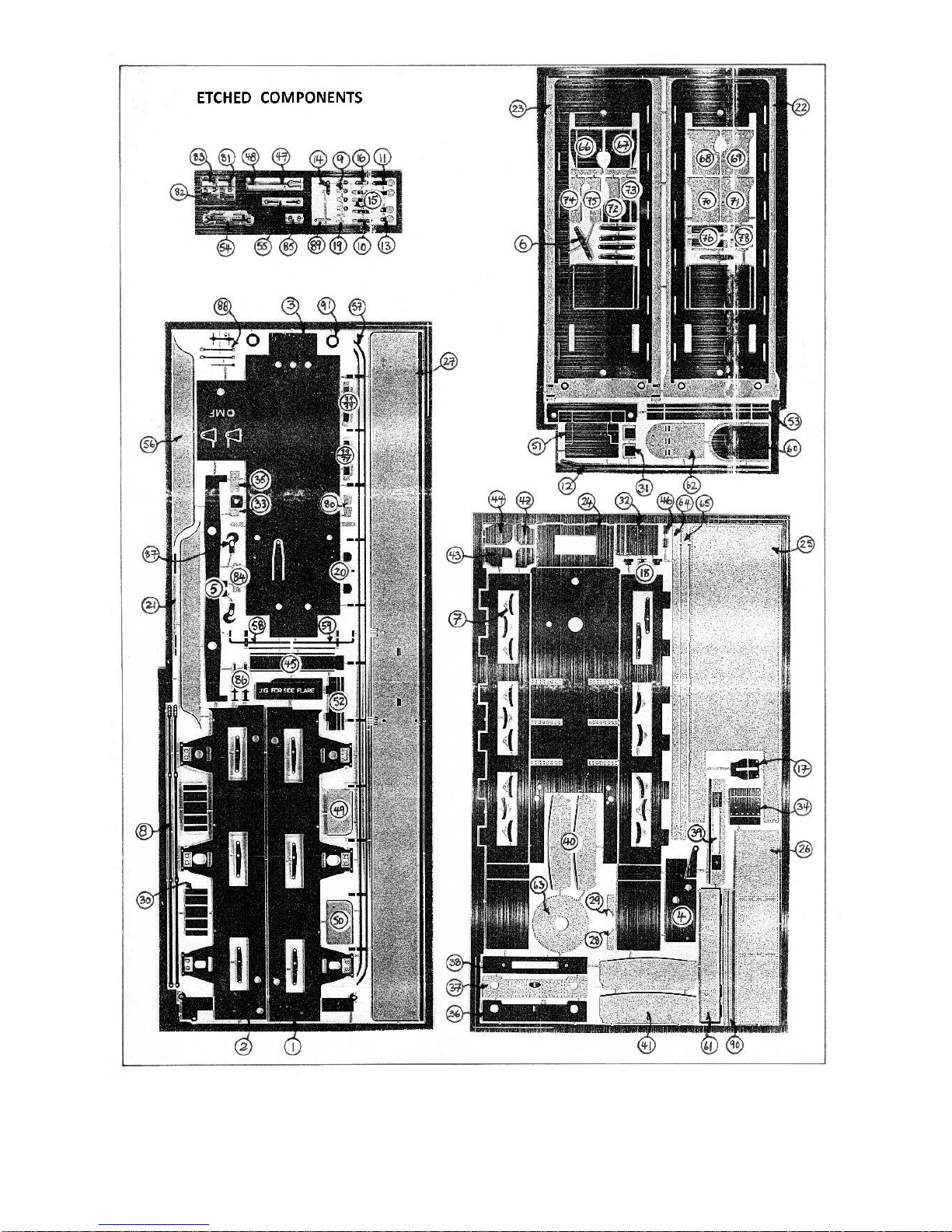
SECTION 2: CONSTRUCTING THE CHASSIS.
Start by folding the side frames (parts 1 & 2) at 90° along the half-etched lines. Emboss the etched dimples in the side
frames to make the rivet detail. Check that the bearings fit in appropriate slots (Fig. 5) carefully opening the slots with
a needle file if necessary and solder the rear pinpoint bearings in place. Construct appropriate hornguide ties as in Fig.
2 and fold up the brackets for the front brake cross shaft, strengthening the folds with a fillet of solder.
Emboss the rivets on the well tank (part 3), fold up along the half-etched lines and solder the seams. Fold down the
brackets for the vacuum pipe and the rear scoop cross shaft.
Construct the compensation beam by soldering the two halves (part 5) together. Cut the piece of 1/16" brass tubing
to fit between the sides of the well tank and solder the beam on it, centrally. Fit the beam inside the well tank using
the piece of 1/16" brass wire as the pivot.
If appropriate, attach the plate (part 17) to the front of the water scoop casting, first bending it through approximately
10° along the half-etched line, Sow attach the water scoop to the well tank and add the stays from 0.45mm wire
passing them through the holes in the front plate and the slots in the well tank bottom and attaching them to the
scoop at the rear aligning them with the grooves in the scoop casting. Add the scoop cross shaft from 0.45mm wire
and fit part 14 at the same time.
Make up the wheelsets carefully setting the back to back measurement with a gauge. Assemble the side frames and
the well tank bolting them together with 10 BA bolts and nuts through the holes at the front and back. Check that the
assembly is square and that the top surface of the assembly is flat. Remove one of the front bolts, pivot the frames
apart, fit the wheelsets and refit the bolt. Sow check that the compensation works properly and that the chassis is
level. The height can be adjusted by filing the ends of the compensation beam and the side play on the centre axle can
be limited by using the washers (part 91),
When you are satisfied with the mechanical performance of the chassis carefully solder the sideframes to the well
tank, avoiding soldering the bolts, then remove the bolts and complete the soldering. Fold up the scoop cross shaft
bracket on the front plate (part 4) and solder it in position.
Complete the scoop operating mechanism by assembling parts 13, 15, 12 & 16 as shown in Fig.1. Attach the steam
brake cylinder casting and assemble the front brake cross shaft as in Fig.1 using parts 9,10 & 11.
Before proceeding any further with the chassis the basic shell must be constructed as described in section 3.
Solder together the 3 pieces (part 20) to make the vacuum pipe drip trap. Drill out the small holes on either side to fit
0.7mm wire and construct the vacuum pipe as shown in Fig. 4 soldering the rear bracket inside the well tank and
bending the pipe to align with the vacuum pipe on the rear buffer beam. Similarly make the steam heating pipe as in
Fig.3 soldering it to the bottom of the well tank on the opposite side to the vacuum pipe.
Solder the brake shoes (part 7) together, back to back, and solder them between the hangers (part 6) using 0.45mm
wire as pins. Solder the hangers in place suspending them from pieces of 0.45mm wire as in Fig. 1, Check the clearance
between the brake shoes and the wheels making any necessary adjustments. Using 0.45mm wire as cross shafts fit
the pull rods (part 8) and attach them to part 9 using pieces of 0.45mm wire as pins.