Bradley MG Series Manual de usuario

Installation
215-1322 Rev. W; ECN 13-08-025
© 2014 Bradley
Page 1 of 15 4/9/2014
MG-3/IR
Express®Lavatory
System - MG Series
with Adaptive
Infrared Control
Table of Contents
Pre-Installation Information ...................2
Dimensions..................................3
Supplies Required ...........................3
Rough-Ins ...................................4
Installation ............................5–8
Components..........................9–10
Cleaning and Maintenance ................11
Adaptive Infrared Troubleshooting ...........12
Solenoid Valve Troubleshooting .............13
Navigator®Mixing Valve Troubleshooting ......14
P.O. Box 309, Menomonee Falls, WI 53052-0309
Phone: 800.BRADLEY (800.272.3539) Fax: 262.253.4161
bradleycorp.com

MG-3/IR Installation
24/9/2014 Bradley • 215-1322 Rev. W; ECN 13-08-025
IMPORTANT!
Read this entire installation manual to ensure proper installation. For optional
soap dispenser, refer to Installation Instructions for Express®Lavatory System
MG-Series document 215-1585. When finished with the installation, file this manual
with the owner or maintenance department. Compliance and conformity to local
codes and ordinances is the responsibility of the installer.
Separate parts from packaging and make sure all parts are accounted for
before discarding any packaging material. If any parts are missing, do not begin
installation until you obtain the missing parts.
Make sure that all water supply lines have been flushed and then completely
turned off before beginning installation. Debris in supply lines can cause valves to
malfunction.
Turn OFF electrical power to the electrical outlets, then unplug all electrical
units prior to installation. Electrical power MUST remain off until installation is
completed. After installation is complete, turn on the water supply first, then turn
on the electrical power.
Hardware supplied by installer must be appropriate for wall construction. Wall
anchors used must have a minimum pull-out rating of 1,000 lbs. Overtightening
fasteners can damage the Terreon®material. Use caution when tightening bowl and
sprayhead fasteners.
Product warranties may be found under “Product Information” on our web site at
www.bradleycorp.com.
Installation
THIS
SIDE
UP
Packing List
•
•
•
•
Installation MG-3/IR
Bradley • 215-1322 Rev. W; ECN 13-08-025 4/9/2014 3
84"
(2134mm) 72"
(1829mm)
30"
(762mm)
30"
(762mm)
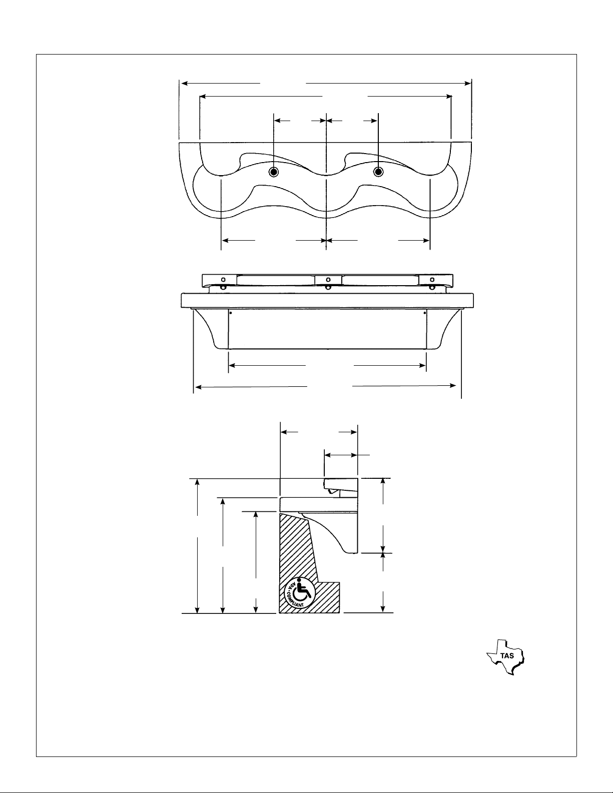
Dimensions
57"
(1445mm)
77"
(1956mm)
22"
(559mm)
39"
(991mm)*
33½"
(851mm)*
29½"
(749mm)*
17½"
(445mm)*
21½"
(546mm)*
9½"
(241mm)
* Subtract 4" from all vertical dimensions for Juvenile Height Mounting.
Subtract 3.5" from all vertical dimensions for TAS Juvenile Height Mounting (grades Pre-K through 5 or 6).
Subtract 1.5" from all vertical dimensions for TAS Juvenile Height Mounting (grades 6 through 8 or 9).
Supplies Required:
• (8)3/8" wall anchors, bolts and 1" min. O.D. washers to mount main frame and bowl to wall (minimum pull-out rating of
1,000 lbs.)
• 1/2"nominalcoppertubingforhotandcoldsuppliesand1½"NPTdrainpiping
• 110voltelectricaloutletfor110/24VACplug-intransformer(supplied)
• 240/208voltor277voltelectricaloutletforoptionalelectricaltanklesswaterheater
15"
(381mm)
15"
(381mm)
MG-3/IR Installation
44/9/2014 Bradley • 215-1322 Rev. W; ECN 13-08-025
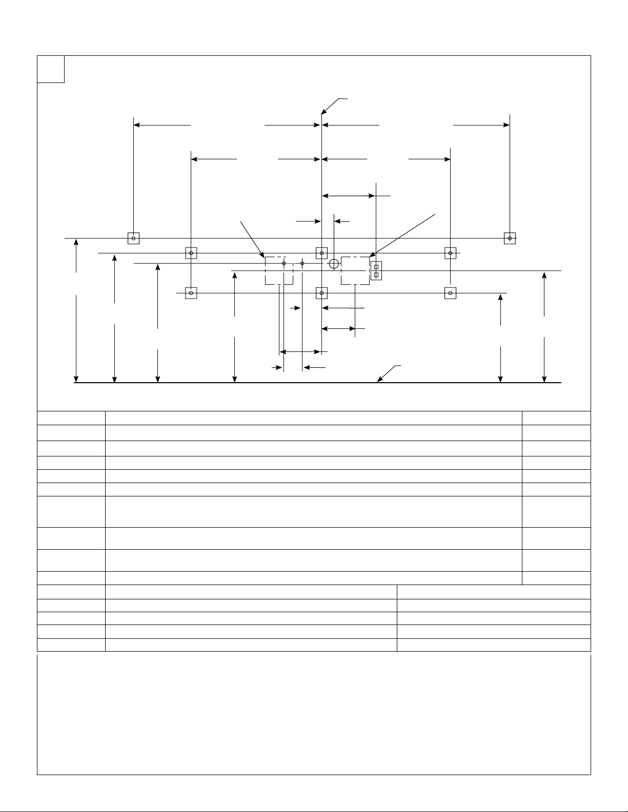
1Rough-Ins
4" (102mm)
FLOOR
CENTERLINE OF FIXTURE
APPROX. DIMENSION
A,E
B
7-1/4" (184mm)
H
G
28¼"
(718mm)*
26"
(660mm)*
31½"
(800mm)*
40½" (1029mm)
CODE DESCRIPTION QTY.
A3/8" Wall Anchors with a minimum pull-out force of 1,000 lbs. for Bowl 2
B3/8" Wall Anchors with a minimum pull-out force of 1,000 lbs. for Main Frame 6
C1 ½"NominalCopperTubingHotSupply,stubout2"fromwall 1
C2 ½"NominalCopperTubingColdorTemperedSupply,stubout2"fromwall 1
D1½"NPTDrain,stubout2"fromwall 2
E
Onthebowlback,measurethedistancebetweenthe¾"bowlmountingholes.Dividethismeasurement
inhalf.Measureandmarkthisdimensiononthewalltotheleftandtherightofthecenterline.Installtwo
3/8"wallanchorswithaminimumpull-outratingof1,000lbs.(suppliedbyinstaller)atlocationsmarked.
2
FWater Heater Option #1: Rough in appropriate electrical supply per local code (recommended location for
240/208V or 277V electrical box [6"L x 3"W x 6"H shown]) 1
GWater Heater Option #2: Rough in appropriate electrical supply per local code (recommended location for
240/208V or 277V electrical box [6"L x 3"W x 6"H]) 1
H 110V GFCI Protected Electrical Outlet 1
RIM HEIGHT * VERTICAL HEIGHT ADJUSTMENTS FIXTURE STYLE
33½" None Standard Height
32" Subtract1½" TAS, Grades 6 through 8 or 9
29½"Subtract 4" Juvenile Height
30" Subtract3½" TAS, Pre-K through 5 or 6
B
B B
D
F2¾"
(70mm)
BB
A,E
19½"
(495mm)*
12"
(305mm)
28"
(711mm)
NOTE: The Express®Lavatory System with Adaptive Infrared Control (model MG-3/IR) must have a rim height no higher
than 34" above finished floor to be compliant with Americans with Disabilities Act (ADA). When mounted at 33½" rim
height, the MG-3/IR Express®meets ADA, ANSI and UFAS requirements for barrier-free clearances, reaches and
controls. Always check local codes and ordinances for compliance.
24"
(610mm)*
28"
(711mm)
APPROX. DIMENSION
40½" (1029mm)
24"
(610mm)*
4" (102mm)
9" (229mm)
C2
C1

Installation MG-3/IR
Bradley • 215-1322 Rev. W; ECN 13-08-025 4/9/2014 5
Secure the bowl to the wall anchors
with two 3/8" bolts and washers. Do
not overtighten bolts.
B
Attach the front of the bowl to the frame
using the four ¼-20 x ½" pan-head
screws and washers provided. Do not
tighten screws at this time.
A
Tighten the screws to secure the bowl
assembly to the frame. Do not overtighten.
If necessary, adjust sprayhead body to fit
closely to the wall by adjusting the sprayhead
mounting bolts. Refer to the components
illustration for bolt locations.
C
2Mount the Frame
3Install the Bowl
Anchoring the frame to a wall that is not flat may cause the frame to
bend, making it difficult to reinstall the access panels. If necessary,
use shims to compensate for wall distortion.
Loosen, but do not
remove the bottom
panel screws.
A
Remove the top access panel
screws and washers and
remove the access panel.
B
Once you have positioned
the frame such that it is level
and flat against the wall or
shimmed, use the 3/8" bolts
and washers (6 places) to
mount the frame to the wall.
C
If the fixture has a soap option, refer to the soap
system installation manual (215-1585) before
installing the bowl assembly.
MG-3/IR Installation
64/9/2014 Bradley • 215-1322 Rev. W; ECN 13-08-025
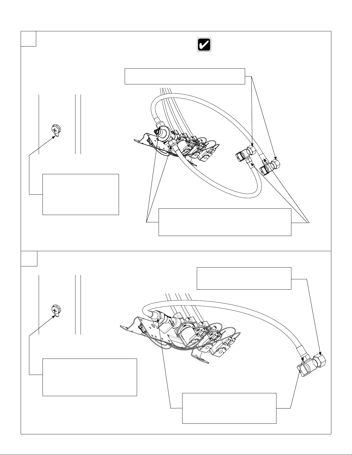
4a Connect the Supply — Hot and Cold Supply
4b Connect the Supply — Single Tempered Supply
The letter “H” on the Navigator Mixing
Valve indicates hot water supply inlet.
Loosen but do not remove
the two mounting screws
holding the valve bracket
to the frame.
Slide the valve bracket up
and lift it from the frame.
A
Connect one end of each hose to the Navigator
valve (one on the hot side, one on the cold side).
Connect the other swivel end to the stops.
C
Attach the stops onto the hot and cold wall
stub-outs.
B
Loosen but do not remove the two
mounting screws holding the valve
bracket to the frame.
Slide the valve bracket up and lift
it from the frame.
A
Connect one end of flexible hose
to the tempered line adapter.
Connect the other swivel end to
the stop.
C
Attach the stop onto the tempered
wall stub-out.
B
Installation MG-3/IR
Bradley • 215-1322 Rev. W; ECN 13-08-025 4/9/2014 7
To Drain
Stub-Out
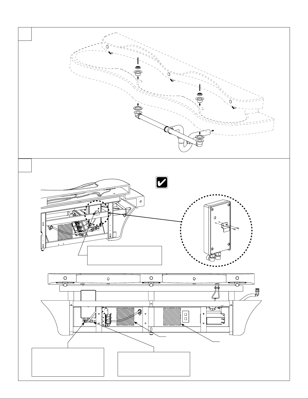
5Install the Drains
6Connect Optional Electric Tankless Water Heater
240/208 or 277 voltage is required for hot water heater.
Refer to the installation manual provided with the hot
water heater for further installation information.
Connect the ½" flexible hose
from the cold water supply
stub-out to the hot water
heater inlet.
B
Connect the ½" flexible hose
from the hot water heater
outlet to the supply inlet on
the solenoid valve assembly.
C
Hang the water heater on the
rear frame member to the right
of the vertical frame member.
A
Recommended
electrical box
location Optional
electrical box
location
MG-3/IR Installation
84/9/2014 Bradley • 215-1322 Rev. W; ECN 13-08-025
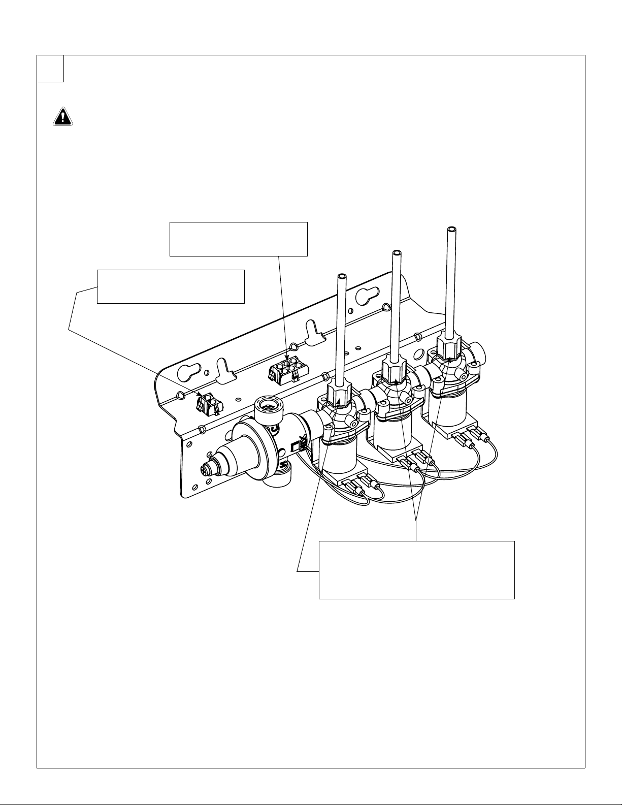
7Connect the Electrical and Tubing
Connect the circuit plug from
the transformer to the female
transformer circuit plug.
B
Connect the sensor circuit
plug from the sprayhead to
the solenoid circuit plug.
A
WARNING:
The Express®control must be connected with the 24 VAC Class II transformer provided. Connections to
110 VAC can cause personal injury and will result in damage to the electronics.
Connection of leads other than shown may cause permanent damage to the sensor.
Loosen the compression nuts.
Push the sprayhead supply tubes firmly
into the tube connectors until they are
fully seated.
Tighten the compression nuts by hand.
C
Installation MG-3/IR
Bradley • 215-1322 Rev. W; ECN 13-08-025 4/9/2014 9
Reinstall the valve bracket.
Turn on the water supply and check for leaks. Turn on the electrical power to the electrical outlet and pass your hand in front
of each station’s sensor until all the air is purged from the lines and water is flowing smoothly. Reinstall the access panel.
START-UP NOTE: Wait two full minutes after making the power connection before using the lav. The sensors will take up to
eight full minutes (while not in use) to adapt to the bowl if another object is detected during the two-minute start-up period.
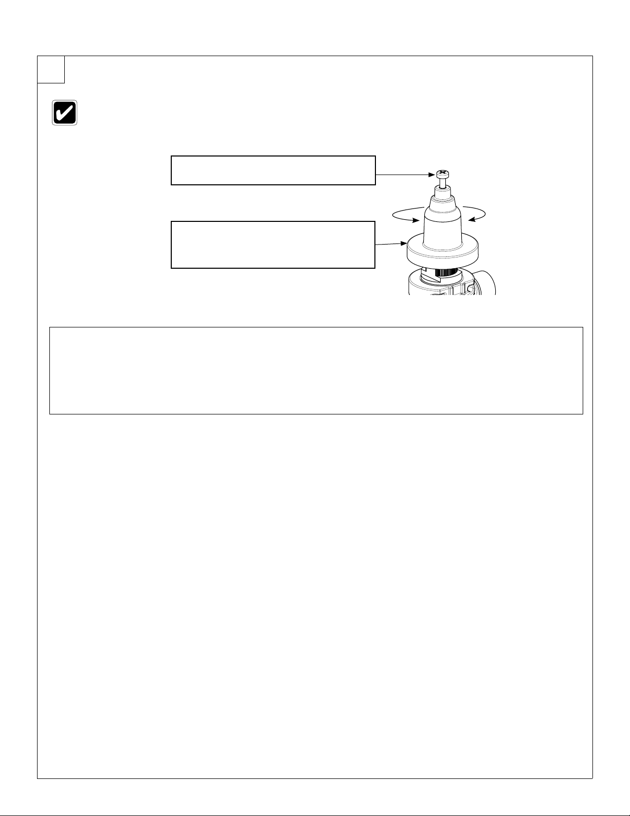
Check the temperature when approximately 1.0 GPM water flow is reached and adjust if necessary (the range of the valve is
95°F–125°F (35°C–52°C).
C
H
C
ALoosen Cap Screw about ¼" (4-6 turns)
and lift up cover (do not remove).
B
Using cover, turn cartridge gently until
desired water temperature is reached.
Do not turn past stops as this may
damage unit. Push cover down and
tighten screw.
This valve is NOT factory preset. Upon installation, the temperature of this
valve must be checked and adjusted to ensure delivery of a safe water
temperature. Water in excess of 110°F (43°C) may cause scalding.
8Adjust the Temperature

MG-3/IR Installation
10 4/9/2014 Bradley • 215-1322 Rev. W; ECN 13-08-025
Components
STAINLESS STEEL
ACCESS PANEL
(186-1262)
SPRAYHEAD
MOUNTING BOLTS (5)
PLUG-IN
TRANSFORMER
110/24 VAC CLASS II
TRANSFORMER
S83-152
SPRAYHEAD BODY
(PART NUMBER VARIES WITH
COLOR OF UNIT. CONTACT
YOUR LOCAL BRADLEY REP.
FOR ASSISTANCE).
BOWL
(PART NUMBER VARIES
WITH COLOR OF UNIT.
CONTACT YOUR LOCAL
BRADLEY REP. FOR
ASSISTANCE).
END CAP (RIGHT)
(PART NUMBER VARIES
WITH COLOR OF UNIT.
CONTACT YOUR LOCAL
BRADLEY REP. FOR
ASSISTANCE).
END CAP (LEFT)
(PART NUMBER VARIES
WITH COLOR OF UNIT.
CONTACT YOUR LOCAL
BRADLEY REP. FOR
ASSISTANCE).
1/4"-20 x 1/2"
PAN HEAD
SCREW (qty. 4)
(160-389)
1/4"-20
WASHER
(qty. 4)
(142-002DB)
BOWL MOUNTING
HARDWARE
Otros manuales para MG Series
2
Este manual sirve para los siguientes modelos
1
Tabla de contenidos
Otros manuales de Baño de Bradley


Manuales populares de Baño de otras marcas


Better Bathrooms
Better Bathrooms BUN/BeBa 27555/78725 Manual de usuario

American Standard
American Standard CONCEPT Cube TF-2704 Manual de usuario

BIOLAN
BIOLAN ECO Manual de lista de piezas

Thetford
Thetford C260 Series Manual de usuario

KELISS
KELISS T162A Series Manual de usuario

Kohler
Kohler K-22241K Instrucciones de montaje


