Borg & Overstrom u1 Manual de usuario

u1 40L - Install & Operation Manual
GB
Dispense options
Telephone
+44 (0)1362 695 006
Email
sales@borgandoverstrom.com
borgandoverstrom.com
Synergy House
Fakenham Road
Morton On The Hill
NR9 5SP
Chilled
Ambient
Chilled, Ambient & Sparkling
Contents 2 Model Overview
3 Component/Feature Overview
5 Installation
15 Operation
18 Maintenance & Cleaning
21 Advanced Troubleshooting
23 Exploded Diagrams & Parts List
26 Technical Information
29 Declarations of Conformity

Install & Operation Manual
Borg & Overström GB2
Model Overview
COOLING SYSTEM Stainless steel direct chill coil
encased in a solid-block system
for instant response cool down
action. Ultra efciency compression
system with capillary control.
Environmentally friendly R134a
refrigerant.
COLD TEMPERATURE 2°C - 10°C.
OUTPUT PER HOUR 40 litres cold and sparkling at
<10°C.
DISPENSE Swan Neck Faucet with
ergonomically designed and situated
light touch sensitive controls.
MAX RUNNING POWER
CONSUMPTION
570 watt (during recovery), Rated
input 277 watt.
POWER SUPPLY 230V AC (50 Hz)
WATER CONNECTION Mains in - 1/4” Push Fit/ Faucet -
1/4” Push Fit
CO2 CONNECTION 1/4” Push Fit
DIMENSIONS (w x d x h) 330 x 370 x 362mm
WEIGHT 26Kg
CUPBOARD VENTILATION Required
The u1 epitomises cutting-edge design
and innovation with its contoured tap
and compact under-counter unit. This is
our most discreet range and will t into
any environment seamlessly.
The under-counter dispenser is a dry
block cooler carbonator designed
to provide ambient still, chilled and
carbonated water. All the materials and
components are tested during the entire
production process in order to satisfy all
expectations.
Introduction

Install & Operation ManualBorg & Overström GB
3
Component/Feature Overview
Contents:
1 no Electronic Swan Neck Tap
1 no 2/3-Button Membrane Control Panel
1 no 1.0m x 6mm Insulated Water Pipe
1 no Connector Box
1 no 4mm Self Adhesive Clip
1 no Fixings Set
Please Note:
Mains Installation Kit & Filters are supplied as extra items according to individual ordering requirement.
U1 Tap - Major Components
Swan Neck
Threaded Stem & Back Nut
Water Pipe
Electrical Connection
Main Body
Faucet
Membrane Control Panel

Borg & Overström GB
4
Install & Operation Manual
Major Components
Contents:
1 no Undercounter Unit
1 no 2.0m Power Cord Set
1 no 1.0m Faucet Connection Harness
1 no Co2 Regulator with Gauge & Connection
tube (Sparkling option only)
1 no Stainless Steel Drip Tray (c/w with Drain
Outlet Cap)
1 no Ventilation Ducting Kit
1 no Ventilation Grille
Faucet Connection Harness
CO2 Inlet
Water Inlet
Top Panel
Power Connection
Unit Carry Handle
Side Panel
Front Panel
Water Outlet
Eliwell Control Panel

Install & Operation ManualBorg & Overström GB
5
Installation
Tap Installation
1
Identify a suitable location for the undercounter unit. It should
be positioned within 1.0m of the faucet, and within 2.0m of
suitable services connections. Allow enough space to t the
ventilation ducting system.
Service Requirements
Water: Mains potable water – internally regulated to 1.3bar. Min
mains pressure 1.3bar.
Electricity: 13A supply – Earth Leakage Protected.
2
33 - 35mm
3
187mm
4
When planning and providing
for the connection to the
services, always allow for
easily accessible service isolator
ttings and for the position of an
external water lter.
Identify a suitable position for the
swan neck faucet. A 33-35mm
(max) hole is required.
When positioning to drain over
an existing sink bowl, allow for
the reach of the swan neck or
otherwise the position of any
optional drip tray.

Borg & Overström GB
6
Install & Operation Manual
400mm
Also allow for the height of
the swan neck under any
overhanging cupboard/shelf.
Carefully form the needed hole,
using the correct type of cutter
for the work surface material.
Observe all local occupational
health and safety requirements.
Remove the back nut and washer
from the faucet and carefully
feed the connecting pipe tail
and ribbon cable through the
hole formed in the work surface.
Ensure the sealing O ring is pre-
tted in the base of the faucet.
You may want to apply a thin
bead of silicone sealant also.
With the faucet control panel in
the right position, carefully ret
the back washer and nut. Take
care not to over-tighten.
5
9
8
Allow for the space needed
for forming the required hole.
Relate the selected position to
the underneath of the counter
and check for any obstructions.
Allow sufcient space for tting
the back nut to the faucet stem.
67
10
78mm
70mm
Install the ventilation system
using the instructions/templates
provided.
11 12
Fit optional Drip Tray at this
stage (if selected).
Once the ventilation system is
installed, position the unit on the
ducting as instructed and follow
the connection steps on page 9.
13

Borg & Overström GB
7
Install & Operation Manual
Tap Dimensions
135mm
414mm
188mm
42mm
260mm
33.3mm

Borg & Overström GB
8
Install & Operation Manual
Driptray Dimensions
250mm/ 9¹³/16”
12.7mm/ ½” Waste Spigot
110mm/ 4 ¹¹/32”
220mm/ 8 ²¹/32”
12.7mm/ ½”
Waste Spigot
180mm/
7 ³/32”
150mm
/
5 ²9/32”
75mm/
2 ¹5/16”
Borg & Overström GB
9
Install & Operation Manual
Ventilation System Installation
When Borg & Overström u1 undercounter
units are installed inside a cabinet or
housing, adequate ventilation is
recommended to ensure that they operate
satisfactorily.
During a cooling cycle it is normal for the
unit to produce heat, and the purpose of
ventilation is to provide a supply of air
that can absorb the generated heat which
would otherwise accumulate inside the
cabinet or housing, and reduce the cooling
performance of the unit. The amount of heat
generated by the cooling cycle depends
directly upon the amount of usage – the
higher the usage, the more heat produced.
To provide adequate ventilation we
recommend that air grilles/vents are tted
as supplied (or vent apertures formed) in
the cabinet to allow an airow as shown
below. Normally this should be enough for
all situations.
In conjunction with an inlet vent grille set into
the front of the plinth, it is recommended that
a ducting box and duct is installed in the
base of the cabinet. Another slot located in
the base is responsible for allowing airow
past the condenser positioned at the rear of
the dispenser. Instructions for installing the
ventilation system are as follows:
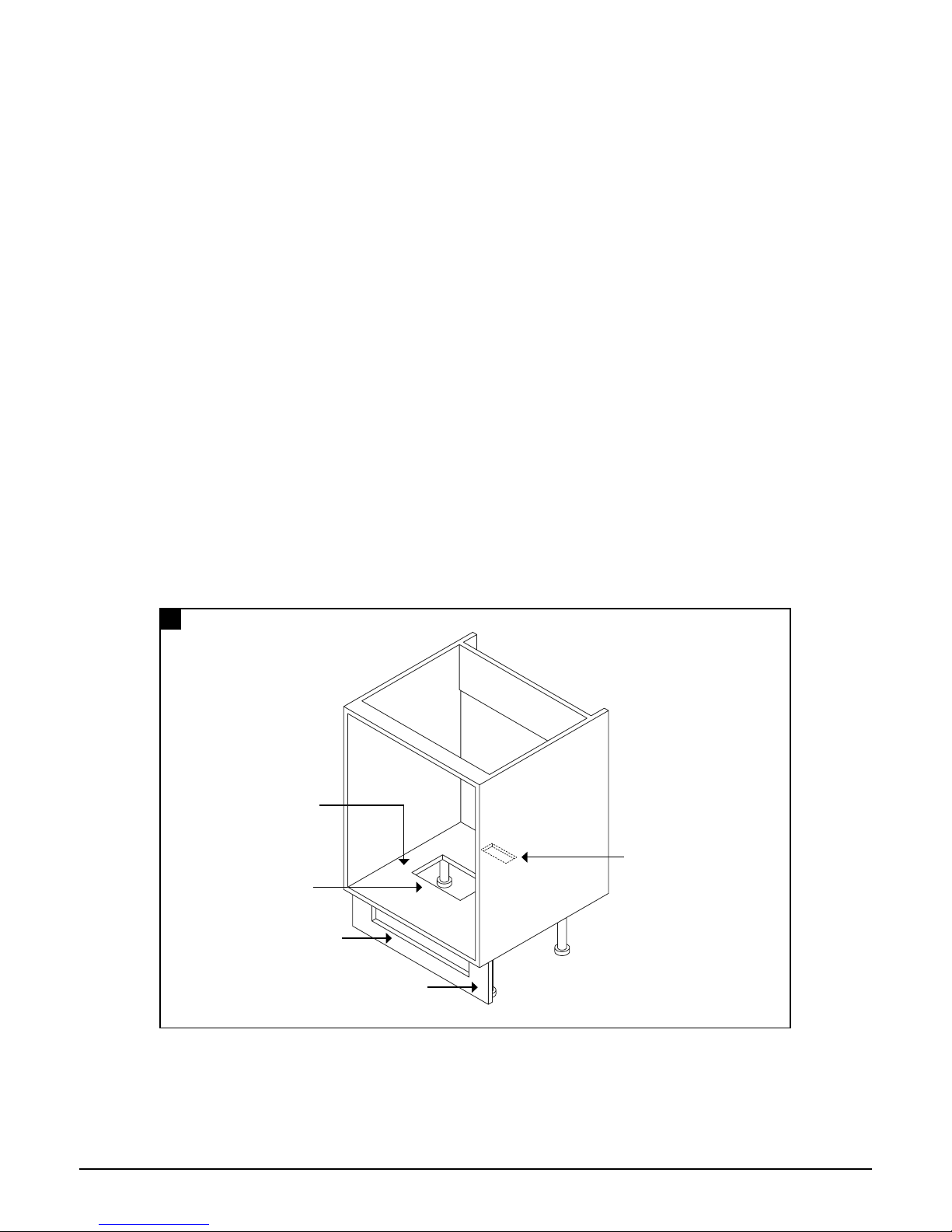
Using the supplied templates, cut the bottom and kickboard panel of the installation cabinet.
Kickboard Cutout
Bottom Cutout
(To align with vent
in bottom of unit)
Kickboard Panel
1
Bottom Panel
Rear Bottom Cutout (To
align with ducting at rear
of unit)

Borg & Overström GB
10
Install & Operation Manual
Insert ducting box into its cut slot in the Bottom panel. Then insert the air ducting into the ducting box until it reaches its limits.
Then cut the air ducting so that it is ush with the kickboard.
Centrally locate the ventilation grille over the kick board cut out, then using self tapping screws, secure the kick plate.
The unit must be positioned accurately over the air ducts to ensure optimum airow.
Ducting Box
Air Ducting
Air Flow
Air Flow
2
3
4
Align duct with
rear cut out
Rear Cut
Out
Otros manuales para u1
5
Tabla de contenidos
Otros manuales de Enfriador de Borg & Overstrom


