Blue Sea Systems M2 OLED Manual de usuario

M2 OLED Bilge Monitor Instructions
PN 1842
Installation Checklist
• Check for components included
• Read Warning and Cautions
• Read page 3 for mounting instructions
• Read System Overview, Mounting Considerations, Detailed Wiring,
and Sensing Description
• Follow Initial System Setup instructions
• Congure Displays
• Congure Alarms
• Congure Relays
Specications
Display Size 55mm x 28mm
Power Supply 7V–70V DC
Power Consumption 0.3W–1.0W*
Alarm/Relay Notiation Run time per hour
Cycles per 24-hour
Cycle Counter
Cycle Counter
Compatible with bilge monitors with external oats switches
or with automatic bilge switches that indicate on status
via a 12V output.
* Variable with voltage, display intensity, and sleep mode
Regulatory
Monitor face is IP66 – protected against powerful water jets
when installed according to instructions
Warning and Caution Symbols
WARNING: The symbol refers to possible injury to the user or
signicant damage to the monitor if the user does not follow the procedures.
CAUTION: The symbol refers to restrictions and rules with regard
to preventing damage to the monitor.
WARNING
• If you are not knowledgeable about electrical systems, have an
electrical professional install this unit. The diagrams in these
instructions pertain to the installation of M2 Digital Meters and not
to the overall wiring of the vessel.
• If an inverter is installed on the vessel, its power leads must be
disconnected at the battery before the monitor is installed.
• If an AC generator is installed on the vessel, it must be stopped
and rendered inoperable before the monitor is installed.
• Verify that no other DC or AC sources are connected to the vessel’s
wiring before installing the monitor.
CAUTION
The back of the unit is not waterproof. Do not install where the back
of the monitor is exposed to water.
Components Included
M2 Head Unit Surface Mount Gasket
Mounting Ring
Surface Mount Bezel
and Seal
Mounting Nut
Flat Mount Bezel
Screwdriver
Retail Package Only
Connector
Bezel
Mount
Footer
Header
Carrier
Mount
#6-32 x 1/4"
Flat Head
Machine Screws
(4X)
#6-32 x 3/8"
Flat Head
Machine Screws
(4X)
Surface Mount Cover Flat Mount Clamp
Panel
Frame
360 Panel Mounting Kit (PN 1525 sold separately)
1

Mounting Considerations
M2 Digital Monitors have three mounting methods: surface mount, at panel mount, and 360 panel mount. When surface mounted per instructions the
unit face is waterproof to IP66. Flat panel and 360 panel mounting systems are not waterproof. The unit should not be at panel or 360 panel mounted
if used in an exposed location. For all mountings, the back of the unit is not waterproof and must be kept dry.
Installation
1. Make all connections to the monitor’s terminal block before connecting the terminal block to the unit.
Keep hands away from the terminal block when applying power to the monitor.
2. As the nal DC connection, insert a fuse into the in-line fuse holder on the wire to the positive (+) battery terminal.
Mounting Templates
Flat Mount
3.34" (84.8mm)
3.00" (76.2mm)
3.00" (76.2mm)
3.34" (84.8mm)
Surface Mount
3.40" (86.5mm)
3.46" (87.9mm)
Ø2.125"
(54mm)
2

STEP 1
Panel
Frame
360 Panel
Mount
Carrier
Use 1/4"
Mounting
Screws
STEP 2
Footer
Panel
Frame
Bezel
Header
Snap header
and footer
into mounting
clips and post.
Snap the
mounting bezel
into place
with the flat
edge up.
STEP 3
Panel
Frame
BezelFooter
Header
M2
Head
Unit
Mounting
Ring and Nut
Mounting
Substrate
Clamp
Flat
Mount
Bezel
M2
Head
Unit
Mounting
Ring and Nut
Mounting
Substrate
M2
Head
Unit
Surface
Mount
Bezel
and Seal
Mounting
Ring and Nut
Surface
Mount
Gasket
Surface
Mount
Cover
NOTE: During
installation use cover
to align the bezel
and gasket
Flat Mount
Surface Mount
360 Panel Mount PN 1525
3

Bilge Functions (1842)
Monitor up to four bilge pumps. Provides High/Low level alarms for each channel.
Connections
IMPORTANT! The Sensing Description section of this manual gives important details to the location of sensors in the AC and DC electrical
systems of the boat. Improper location and conguration of sensors can result in erroneous readings and possible damage to components.
Pin-out Table
1842 Connector Pin Assignment Table
8 Pin Connector* Function
1 Required Connection
2 Required Connection
*The 8 pin low voltage connector supports wire sizes from 16-26 AWG
3
4
5
6
7
8
DC Negative
DC Supply
Relay DC Out to Load
Relay DC +
Bilge Pump 1
Bilge Pump 2
Bilge Pump 3
Bilge Pump 4
USB Micro USB Port
4
Monitor Power Supply Connections
All monitors must have pins 1 (DC Negative) and 2 (DC Supply) connected. These pins are used to provide power to the monitor. Connect pin 1 to
ground and pin 2 to a 12V to 48V power source.
Bilge Connections
The 1842 Bilge Monitor will register any bilge activity anytime the bilge input is greater than 5 volts. The inputs can be connected directly to a oat
switch or the bilge motor supply.
Note: The 1842 Bilge Monitor is not compatible with most automatic style bilge pumps.

1842 Bilge Pump Monitor
12345678
Battery
SPDT Switch
*
Float Switch
Bilge Pump
Busbar
Relay
(7713 12V)
(7717 24V)
Alarm (1070) LED
(8033 Amber)
(8171 Red)
(8172 Green)
OROR
Float Switch Connections
Detailed Wiring
5
12345678
Battery
* Use bilge pump manufacturers recommended fuse.

4
3
Relay Supply
Pin 4 voltage connections are only required if the
relay is used or if the battery monitor function is used.
Optically isolated relay control
500mA DC Maximum current
M2 Relay Connections
M2 Meters contains an internal MOSFET relay that can drive external DC loads up to 0.5A. The input is protected with a thermally activated auto-reset-
ting fuse that will protect against shorts. In addition, an inline fuse rated at 5A should be used to protect against shorts. In typical applications, a power
source is connected to the Relay+ pin and a load is connected to the Relay Out to Load connection.
External LED
An external LED such 8171 can be connected to the Relay Output terminal. If the system is going to operate at
more than 24V nominal, an additional 4K Ohms of resistance should be placed in-line with the LED.
12345678
LED,
12V/24V
8033, Amber
8171, Red
8172, Green
LED
Supply
8 to 70V
Yellow Wire
Red Wire
6

7
12345678
AB
NOTE: For optional SPST
switch connections
Wire connections are the same
as the SPDT, ON-ON except
the Ground is omitted.
No Connection
orange
green
brown
CONTROL (red)
GROUND (black)
LED OUTPUT (yellow)
12V or
24V DC
Bilge Pump
External Relay
If you need to switch more than 0.5 A, you can use an external relay such as PN 7713, 12V or PN 7717, 24V Remote Battery Switch. Connect the
Relay+ terminal to the red control wire. Activating the internal relay will also activate PN 7713.
NOTE: 9012, 7700, 7701, 7702, & 7703 Remote Battery Switches
are not compatible with the internal relay.
12345678
External
Alarm
Supply
5 to 30V DC
+ Red
- Silver
1070
External Alarm (1070 Floyd Bell Turbo)
The Relay+ terminal can support an external audible alarm. Such as the Floyd Bell Turbo Alarm (1070).

Getting Started
Example Screens From PN 1842 Bilge Monitor
When an M2 Meter is initially powered up, it will display the Blue Sea Systems Logo, its serial number and its Software revision.
After a couple of seconds, the unit will display a high-level System Summary screen.
Pressing any button will display a temporary pop-up menu. Select an option by pressing the button beneath it. The pop-up menu will disappear after the
rst button is pressed.
The menu system is a two dimensional matrix. Pressing the NEXT button will transition the display between the System Summary screen which displays
summary information for each of the “bilge pump” channels.
Press the UP ↑or DOWN ↓arrow buttons to display more detailed information about an input channel or to show a single parameter, such as “B1” in the
display (see example below).
8
Press the Menu button to bring up the Setup menus. Press the UP ↑and DOWN ↓arrow buttons to move the cursor over the options and press the
Select button to see a selected display. To return to the previous display, press the Back button.

9
Conguring the Monitor
Monitor settings can be congured from the Setup menu. This menu can be accessed by pressing the Menu button and then scrolling to and selecting
Setup. Press the UP ↑and DOWN ↓arrow buttons to move the cursor. The different setup options are described below.
Alarm Setup & Control
The meter monitors two different conditions that can active an alarm. The meter monitors the amount of time the bilge is active over the last
60 minutes. The monitor can be set to sound an alarm anytime the monitor exceeds a certain on time. The monitor can also monitor the number of cy-
cles that have occurred in the last 24 hours. Alarms can be set from the Alarm Setup menu. To get there, rst navigate to the Setup menu. Then scroll
to Alarm Setup and press the Select button.
Setting Alarms
The M2 Monitor family provides monitoring capability of bilge input channels. Alarms are triggered if a channel is above or below a certain user select-
ed threshold value. The following example indicates how to setup a run time high alarm.
1. Go to the Alarm Setup menu.
2. Scroll to the desired input channel (i.e., Bilge 1 Hi).
3. Press the Select button and the cursor should start blinking.
4. Set the bilge threshold using the ←and → buttons. (Holding down the buttons allows faster selection)
5. Press the Enter button to save the change or the Cancel button to cancel any change.
In the above example, an alarm will set anytime Bilge 1 is running longer than or equal to 8 minutes.
Clearing Alarms
When an alarm occurs, the buzzer will sound, the red ALARM LED will light, and the screen will display which alarm was triggered, the Alarm set point
and the current value. Pressing any button silences the buzzer and another button press returns to the previous display.
Until the cause of the alarm is resolved, the ALARM LED will remain on and the channel that triggered the alarm will blink.
10
Viewing Alarms Status
For any active alarm, the parameter will ash if it is displayed. To view a complete list of active alarms, press Menu>Setup>Alarm Setup. Any active
alarm will ash. You may have to scroll through the menu to see all of the alarms.
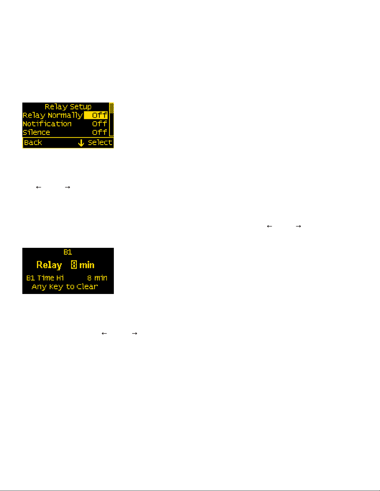
Relay Setup & Control
M2 Monitors provide an option to control an external relay. The M2 can trigger the relay based on runtime in an hour or the number of cycles in 24 hours.
These relay options can be set from the Relay Setup menu. To get there, rst navigate to the Setup menu. Then scroll to Relay Setup and press the
Select button.
Relay Normally On/Off
This setting sets the normal operating state of the connected relay. The options are ON or OFF where ON means the relay is on (contacts closed) in
normal operation and OFF means it is normally off (open contacts). Scroll to Relay Normally, press Select (selection will ash), then press the
LEFT ←or RIGHT →arrow buttons to change the setting. Press Enter to save your selection. Press Cancel to cancel a change.
Notication
The Notication setting controls whether or not a notication is displayed when a relay is activated. Notications will show which relay threshold was
surpassed and for which channel. Scroll to Notication and press Select to change the setting. Press the LEFT ←or RIGHT →arrow buttons to choose
either ON or OFF. ON will display notications and OFF will not. Use this option if you don’t want to be notied that the relay is activating. Press Enter to
save the setting or Cancel to cancel a change.
Silence Relay
Turn this option on if you want the relay to de-activate after the user presses a key on the display. The key press will only de-activate the relay and will
not engage any functions on the monitor. For example, this option could be used to silence an external buzzer. Scroll to Silence and press Select to
change the setting. Press the LEFT ←or RIGHT → arrow buttons to choose either ON or OFF. Press Enter to save the setting or Cancel to cancel
any change.
Viewing Relay Status
To view a complete list of active relays, press Menu>Setup>Relay Setup. Any active relay will ash.
Otros manuales para M2 OLED
8
Este manual sirve para los siguientes modelos
1
Tabla de contenidos
Otros manuales de Monitor de Blue Sea Systems

Blue Sea Systems
Blue Sea Systems M2 OLED Manual de usuario

Blue Sea Systems
Blue Sea Systems M2 OLED Manual de instrucciones

Blue Sea Systems
Blue Sea Systems 1841 Manual de instrucciones

Blue Sea Systems
Blue Sea Systems 1850 Manual de instrucciones

Blue Sea Systems
Blue Sea Systems M2 OLED Manual de instrucciones

Blue Sea Systems
Blue Sea Systems M2 OLED Manual de usuario

Blue Sea Systems
Blue Sea Systems M2 OLED Manual de instrucciones

Blue Sea Systems
Blue Sea Systems 1839 Manual de instrucciones


