Bitzer SE-i1 Manual

CT-110-2
Protection and monitoring device for CS. and HS. screw compressors
Translation of the original document
English....................................................................................................................................................... 2
Schutz- und Überwachungsgerät für CS.- und HS.-Schraubenverdichter
Originaldokument
Deutsch ..................................................................................................................................................... 28
SE-i1
Electrically skilled installer
Elektrisch unterwiesener Monteur

CT-110-22
Table of contents
1 Introduction............................................................................................................................................................3
1.1 Also observe the following technical documents ...........................................................................................3
2 Safety ....................................................................................................................................................................3
2.1 Authorized staff..............................................................................................................................................3
2.2 Residual risks ................................................................................................................................................3
2.3 Safety references...........................................................................................................................................3
2.3.1 General safety references.................................................................................................................. 4
3 Monitoring functions, protective functions and extent of delivery ..........................................................................4
4 Technical data .......................................................................................................................................................7
4.1 Dimensional drawing SE-i1............................................................................................................................8
5 Mounting and activation of the completion sensor kit............................................................................................8
5.1 Mounting the components of the completion sensor kit to CS. compressors................................................8
5.1.1 Mounting of the pressure transmitter to CS. compressors................................................................. 9
5.1.2 Mounting/replacement of oil temperature sensor (PTC) with discharge gas or oil temperature sensor
(NTC) on CS. compressors.............................................................................................................. 10
5.2 Mounting the components of the completion sensor kit to HS. compressors..............................................10
5.2.1 Mounting of pressure transmitters to HS.64 .. HS.85 compressors................................................. 11
5.2.2 Mounting/replacement of oil temperature sensor (PTC) with discharge gas or oil temperature sensor
(NTC) on HS. compressors.............................................................................................................. 12
5.3 Configuring the completion sensor kit with the BEST SOFTWARE ............................................................12
6 Electrical connection............................................................................................................................................14
6.1 Schematic wiring diagrams for CS.65 .. CS.95 compressors:.....................................................................14
6.2 Schematic wiring diagrams for HS.53 .. HS.85 compressors......................................................................18
7 Data communication with the SE-i1.....................................................................................................................26
7.1 BEST SOFTWARE......................................................................................................................................26
7.1.1 Establishing communication via the BEST SOFTWARE ................................................................. 26
7.1.2 BEST SOFTWARE data log ............................................................................................................ 26
7.2 Interface for communication via ModbusRTU.............................................................................................26
8 Troubleshooting and eliminating faults................................................................................................................27

CT-110-2 3
1 Introduction
The protection device SE-i1 monitors the essential op-
erating parameters of the semi-hermetic compact
screw compressors (CS. compressors) and semi-her-
metic screw compressors (HS. compressors) and pro-
tects the compressors from operation under critical
conditions.
During operation, numerous operating data of the com-
pressor can be tracked and evaluated via the integ-
rated interface using the BEST SOFTWARE, for ex-
ample, the position in the application limits diagram.
The data are recorded and allow a specific diagnosis
and optimization of the compressor and system opera-
tion.
In addition, the device can be fully integrated into the
superior control via a Modbus RTU interface. In addi-
tion to reading out the sensor values, the multi-stage
warning and alarm system can be used in many cases
to react to critical operating conditions and to prevent a
compressor cut-out.
This Technical Information describes the protective and
monitoring functions, the electrical connection of the
protection device and the communication with the
BEST SOFTWARE.
1.1 Also observe the following technical documents
• SB-170 Operating Instructions of semi-hermetic
compact screw compressors (CS. series).
• SB-100: Operating Instructions of semi-hermetic
screw compressors (HS.53 .. HS.74).
• SB-110: Operating Instructions of semi-hermetic
screw compressors (HS.85).
2 Safety
2.1 Authorized staff
All work done on the protection devices, compressors
and refrigeration systems may only be performed by
qualified and authorized staff who have been trained
and instructed accordingly. The local regulations and
guidelines will apply with respect to the qualification
and expertise of the specialists.
The protection devices have been built in accordance
with state-of-the-art methods and current regulations.
Particular importance was placed on user safety.
This Technical Information must be kept available near
the refrigeration system during the whole lifetime of the
protection device.
2.2 Residual risks
Compressors and electronic accessories may present
unavoidable residual risks. This is why any person
working on this device must carefully read this docu-
ment!
The following regulations shall apply:
• the relevant safety regulations and standards (e.g.
EN378, EN60204 and EN60335),
• generally accepted safety rules,
• EU directives,
• national regulations.
2.3 Safety references
are instructions intended to prevent hazards. Safety ref-
erences must be stringently observed!
!
!
NOTICE
Safety reference to avoid situations which may
result in damage to a device or its equipment.
CAUTION
Safety reference to avoid a potentially hazard-
ous situation which may result in minor or mod-
erate injury.
WARNING
Safety reference to avoid a potentially hazard-
ous situation which could result in death or seri-
ous injury.
DANGER
Safety reference to avoid an imminently hazard-
ous situation which may result in death or seri-
ous injury.

CT-110-24
2.3.1 General safety references
Use of the SE-i1 in combination with refrigerants of the
A3 (e.g. propane) and A2 safety groups presents a
DANGER
risk of explosion!
The provided protection device contains ignition
sources capable of igniting propane and refri-
gerants of the A3 and A2 safety groups. Install
the protection device outside the hazardous
zone, for example in a tight switch cabinet.
WARNING
Risk of electric shock!
Before performing any work in the terminal box
of the compressor: Switch off the main switch
and secure it against being switched on again!
Close the terminal box of the compressor before
switching on again!
!
!
NOTICE
Potential failure of the protection device and the
motor due to improper connection and/or faulty
operation!
Connect properly according to the schematic
wiring diagrams and check the connections for
tight seat.
The cables and terminals of the PTC control cir-
cuit must not come into contact with the control
voltage or operating voltage!
For work on the compressor once it has been
commissioned
CAUTION
Surface temperatures of more than 60°C or be-
low 0°C.
Risk of burns or frostbite.
Close off accessible areas and mark them.
Before performing any work on the compressor:
switch it off and let it cool down.
3 Monitoring functions, protective functions and extent
of delivery
The SE-i1 monitors the signals of several sensors posi-
tioned on the compressor and compares the measured
values with programmed data.
In any case, it has the following special product fea-
tures:
• Data log
• Real-time clock
• Communication via Modbus RTU
• BEST SOFTWARE
The following table gives an overview of all monitoring
functions, the extent of delivery and further options of
SE-i1.

CT-110-2 5
CS.65..CS.95,
CSHP*,
HS.53*..HS.85
basic sensor kit
CS.65..CS.95,
HS.64..HS.85
with full sensor kit
SE-i1 as SE-C1
replacement
part number:
34705002
SE-i1 as SE-C2
replacement
part number:
34705004
Protective and monitoring functions
Motor protection functions:
• Motor temperature (PTC)
• Rotation direction
• Phase failure
●
●
●
●
●
●
●
●
●
●
●
●
Oil monitoring:
• CS.: oil level
• HS.53 .. HS.74: oil flow
• HS.85: oil flow / oil stop valve
●
●
●
●
●
●
●
●
●
Warning if the recommended
shut-off periods are not com-
plied with
● ● ● ●
Discharge gas or oil temperat-
ure monitoring (PTC, in series
with motor PTC)
● -- ● ●
Discharge gas or oil temperat-
ure monitoring with absolute
temperature (NTC)
➀ ● ➀ ➀
Monitoring of application limits
(via low pressure and high pres-
sure transmitters)
➀ ● ➀ ➀
Low and high pressure switches ➀ ● ➀ ➀
Settings in the BEST SOFTWARE
Preset parameters Compressor type:
"SE-C1 Replace-
ment" or "SE-C2
Replacement"
Serial number of
the compressor
Compressor type,
serial number of
the compressor
Compressor
type: "SE-C1 Re-
placement"
Compressor
type: "SE-C2 Re-
placement"
Required minimum settings -- Refrigerant, ECO
operation
-- --
Further recommended settings Date and time,
system informa-
tion
Date and time,
system informa-
tion, pressure
switch
Serial number of
the compressor,
date, time, sys-
tem information
Serial number of
the compressor,
date, time, sys-
tem information
Other
Wired and tested when leaving
the factory
● ● -- --
Wire bridge required for unused
oil monitoring inputs ③
Yes No Yes Yes
Optional temperature sensor ② ② ② ②
Tab.1: SE-i1: Monitoring functions, extent of delivery and options

CT-110-26
* For the HS.53 and CSHP compressors, the SE-i1 is
exclusively delivered as a separate basic sensor kit
(part number 347 050 02). It must be installed, wired
and connected in the system's switch cabinet!
Use of the SE-i1 in combination with refrigerants of the
A3 (e.g. propane) and A2 safety groups presents a
DANGER
risk of explosion!
The provided protection device contains ignition
sources capable of igniting propane and refri-
gerants of the A3 and A2 safety groups. Install
the protection device outside the hazardous
zone, for example in a tight switch cabinet.
➀ Completion sensor kit
HS.64 .. HS.85, CS.65 .. CS.95:
If the SE-i1 was ordered ex factory with a basic sensor
kit, it can be retrofitted with the completion sensor kit.
Afterwards, all protective and monitoring functions of
the device can be activated and fully used. For this, all
components of the completion sensor kit must be
mounted on the compressor, wired and configured us-
ing the BEST SOFTWARE (see chapter Mounting and
activation of the completion sensor kit, page 8).
When ordering the full sensor kit for the compressors
HS.64 .. HS.85 And CS.65 .. CS.95, all components of
the completion sensor kit are already installed and
electrically connected to the compressor. The comple-
tion sensor kit is not available for CSHP compressors.
The completion sensor kit (HS.64 .. HS.85 And CS.65 ..
CS.95, part number 347 050 03) consists of the follow-
ing components:
• Low pressure and high pressure transmitters with
connecting cables.
• T-pieces for connecting the pressure transmitters to
the high pressure and low pressure connection of
the compressor.
• Discharge gas temperature and oil temperature
sensor (NTC) incl. connecting cable.
• All cable bushings M25x1.5, M20x1.5, M16x1.5 with
hexagon nuts for the terminal box of the compressor.
Mounting and electrical connection, see chapter Mount-
ing and activation of the completion sensor kit, page
8 and see chapter Electrical connection, page 14.
② Optional temperature sensor
For example, for measurements of the suction gas, li-
quid or ambient temperature. Is considered during the
data log.
• Temperature sensor with screw-in thread (part num-
ber 34704101) + cable with plug (part number
34703301).
– 1/8-27 NPTF thread
– Measuring range: -40°C .. +125°C
• Temperature sensor to be placed on the pipe sur-
face (part number 34703301).
– for measurements of the suction gas temperature
on the pipe surface or measurements of the ambi-
ent temperature.
– Measuring range: -30°C .. +105°C
– Enclosure class: IP65
– Cable length: 5 m
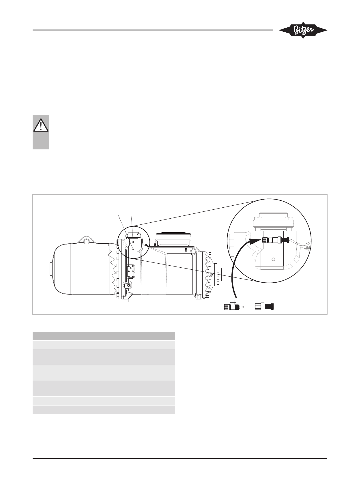
③ Unused oil monitoring inputs
With the setting "SE-C1 Replacement" or "SE-C2 Re-
placement", unused oil monitoring inputs must be deac-
tivated by means of bridges. They must be set between
the following terminals.
Fig.1: Bridge to deactivate the oil monitoring inputs

CT-110-2 7
4 Technical data
Operating voltage 115 .. 230V +10%/-15%, 50/60Hz
Motor voltage 200 .. 690 V AC, ±10%
Operation with frequency in-
verter (FI)
83 .. 690 V AC, +10%, 20 .. 135 Hz
Operation with soft starter 200 .. 690 V AC, ±10%, 50/60 Hz
Required fuse 4A fast-blow
Relay outputs Terminal strip "Relay"
Maximum continuous current 2.5A
Switching voltage 250VAC
Maximum switching current 2.5A
Switching capacity 300VA inductive (C300)
Communication interfaces Terminals "Control", "COM1": RS485 Modbus (RTU)
Terminals "COM2": RS485 sensor bus
RJ12 socket "Service", "COM3": Connection of BEST interface converter
Connection cable for power con-
nections
115 .. 230V
Terminal strip "Supply"
The terminals are suitable for max. 2.5mm2 (AWG12)
Select the cable cross-sections in accordance with the local regulations!
Use copper cables with a sheath quality suitable for at least 85°C. Select the
cable quality according to the installation location, e.g. UV- and/or oil-resist-
ant.
Enclosure class Terminals: IP20
Housing: IP20
Installation in terminal box Can be fixed with screws
Place of installation Allowable ambient temperature: -30°C .. +60°C
Allowable relative humidity: 5% .. 95% (EN60721-3-3 Classes 3K3 and 3C3)
Maximum allowable altitude: 2000m
Toil/dis (oil or discharge gas temp.)
Taux (optional temperature)
NTC temperature sensor
Pdis (high pressure transmitter) Ratiometric, 1 .. 36.5 bar absolute pressure
Psuc (low pressure transmitter) Ratiometric, 0 .. 13.8 bar absolute pressure
EMC The control module complies with the EMC directives 2014/30/EU and
2004/108/EC
Interference immunity:
EN61000-6-1:2007, Immunity for residential, commercial and light-industrial
environments
EN61000-6-2:2005, Immunity for industrial environments
Emitted interference:
EN61000-6-3:2007 +A1:2011, Emission standard for residential, commercial
and light-industrial environments.

CT-110-28
4.1 Dimensional drawing SE-i1
R
Please see manual for complete data. L1:Black
L2:Brown
L3:Blue
Operation
Warning
Service
COM3
NC
NO
C
N
L
PE
Relay
Fault
Comm.
COM2
Not in use
Signal
GND
+24V Supply
GND
Signal
GND
PTC-1
PTC-2
Signal
GND
Signal
GND
+5V Supply
Signal
GND
+5V Supply
Signal
GND
+24V Supply
DATA+
DATA-
GND
Oil flow
Mot.
PTC
Toil/
Tdis
OLC/
Oil stop Taux Pdis Psuc
1 4 8 10 12 14 17 20
Supply
Control
DATA+
DATA-
GND
COM1
134
11
90
53
142
34
45
3
11
4
6
Fig.2: Dimensional drawing SE-i1
5 Mounting and activation of the completion sensor kit
WARNING
The compressor is under pressure!
Serious injuries are possible.
Depressurize the compressor!
Wear safety goggles!
5.1 Mounting the components of the completion
sensor kit to CS. compressors
The wired and connected CS. screw compressors, ex-
cept for CSHP compressors, can be ordered ex factory
either with the SE-i1 basic sensor kit or with the full
sensor kit. Scope of functions, see chapter Monitoring
functions, protective functions and extent of delivery,
page 4.
Therefore, all components of the completion sensor kit
must be mounted to the compressor only if:
• the basic sensor kit is to be upgraded to the full func-
tionality of the full sensor kit.
CT-110-2 9
• the SE-i1 is retrofitted.
• the SE-i1 as a replacement for SE-C1 is upgraded to
the full functionality of the SE-i1.
5.1.1 Mounting of the pressure transmitter to CS.
compressors
During all mounting work:
WARNING
The compressor is under pressure!
Serious injuries are possible.
Depressurize the compressor!
Wear safety goggles!
Connection positions see table 2, page 9.
The following drawings show the connection positions
and the mounting using a CS.95 compressor as an ex-
ample. The positions of the connections 2 (LP) and 3
(LP) can vary, depending on the compressor. For
CS.65..CS.85, see dimensional drawings in the bro-
chures SP-171 (CSH) and SP-172 (CSW).
For the CSHP compressors, the SE-i1 is delivered sep-
arately as a basic sensor kit (part number 347 050 02).
It must be installed, wired and connected in the sys-
tem's switch cabinet, The cables between compressor
and switch cabinet must be protected by a fuse in the
terminal box. The fuse layout depends on the cable
cross-section and the applicable application-related
standards and can therefore not be universally spe-
cified.
High pressure transmitter
• First, screw in the T-piece into the connection posi-
tion 2 (HP) at the compressor.
• Then, screw the high pressure transmitter to the T-
piece and connect the sensor cable.
7/16-20 UNF
1 (HP)
1/8-27 NPTF
2 (HP)
Fig.3: CS.95 compressor: Mounting of the high pressure transmitter
Connection positions CS. compressors
1 High-pressure connection (HP)
2 Additional high pressure connection (HP).
Connection for high pressure transmitter
3 Low pressure connection. Connection for low
pressure transmitter
4/8 Oil sight glass / connection for opto-electronic
oil level switch (OLC-D1-S)
5 Oil service valve
12 Oil temperature sensor (PTC)
Tab.2: Connection positions CS. compressors, pressure transmitters
and NTC sensor

CT-110-210
Low pressure transmitter
• First, screw in the T-piece into the connection posi-
tion 3 (LP) on the compressor.
• Then, screw the low pressure transmitter to the T-
piece and connect the sensor cable.
1/8-27 NPTF
3 (LP)
Fig.4: CS.95 compressor: Mounting of the low pressure transmitter
Legend for connection positions, see table 2, page 9.
5.1.2 Mounting/replacement of oil temperature sensor
(PTC) with discharge gas or oil temperature
sensor (NTC) on CS. compressors
CAUTION
Before mounting or replacing the oil temperat-
ure sensor (PTC), drain the oil from the oil ser-
vice valve (position 5).
See also the notes given in the Operating In-
structions SB-170.
Replace the pre-installed oil temperature sensor (PTC)
with the enclosed discharge gas or oil temperature
sensor (NTC). For this, unscrew the PTC sensor and
mount the NTC sensor at the same position and con-
nect it using the corresponding cable.
4 / 8
1/8-27 UNF
5
1 1/8-18 UNEF
NTC 1/8-27 NPTF
12
Fig.5: CS. compressor: Replacing the PTC sensor with the NTC
sensor
Legend for connection positions, see table 2, page 9.
5.2 Mounting the components of the completion
sensor kit to HS. compressors
The wired and connected HS.64..HS.85 screw com-
pressors can be ordered ex factory either with the SE-
i1 basic sensor kit or with the full sensor kit. Scope of
functions, see chapter Monitoring functions, protective
functions and extent of delivery, page 4.
Therefore, all components of the completion sensor kit
must be mounted to the compressor only if:
• the basic sensor kit is to be upgraded to the full func-
tionality of the full sensor kit.
• the SE-i1 is retrofitted.
• the SE-i1 as a replacement for SE-C1 (HS.64 and
HS.74) or SE-C2 (HS.85) is upgraded to the full
functionality of the SE-i1.
For the HS.53 compressors, the SE-i1 is delivered sep-
arately as a basic sensor kit (part number 347 050 02).
It must be installed, wired and connected in the sys-
tem's switch cabinet, The cables between compressor
and switch cabinet must be protected by a fuse in the
terminal box. The fuse layout depends on the cable
cross-section and the applicable application-related
standards and can therefore not be universally spe-
cified.
Tabla de contenidos
Idiomas:
Otros manuales de Dispositivo de protección de Bitzer


