Bitstorm Bad Boy Xtreme BB-XARC75 Instrucciones de funcionamiento

Xtreme
Installation and
Operation Guide
Revision: 1.6a
BB-XARC75 (Rail / Flat Surface)
BB-XASC75 (1-14 Adapter)
BB-XABC75 (Backstay)
BB-XAPC75 (Pole)
Getting YOU on the web
Models covered:
Hi-Power Wi-Fi Antenna
Rail mount shown

Bitstorm Inc. Bad Boy Xtreme
2www.bitstorm.com
IMPORTANT
Before You Install Your System
Your BAD BOY Wi-Fi system has been completely tested prior to shipment go-
ing through multiple individual and system verifications including Wi-Fi connec-
tivity. Before cutting your cable or installing your system, take a few minutes to
bench assemble your BAD BOY components. Using your computer:
1. verify system operation,
2. familiarize yourself with its behavior when operating, and
3. understand what to expect after installation.
Because a BAD BOY system can be installed in locations not easily accessible,
do not proceed with installation until you have verified that your system is oper-
ating correctly. Contact us for assistance.
System failures after installation are usually caused by applying too much corro-
sion inhibitor to the cable’s connector or incorrect wiring of the Junction Box.
Carefully check that the cable’s colour coded wires match up correctly in your
Junction Box. Your warranty may be affected.
Note: Failure to bench test will indicate your acceptance that your
system was completely and fully operational prior to installation.
Declaration of Conformity
Bitstorm declares that this Bitstorm BAD BOY device is in compliance with the essential require-
ments and other relevant provisions of Directive 1999/5/EC.
This device complies with Part 15 of the FCC rules. Operation is subject to the following two con-
ditions:
1. This device may not cause harmful interference
2. This device must accept any interference received, including interference that
may cause undesirable operation.
Your serial number will be found under the end cap of your Xtreme and is located under the bar
code. You can also find it on the Status tab in Xtreme’s management application. You may be
asked to provide your serial number when requesting support assistance.
________________________________________
Install Date:
Serial Number: ________________________________________
Record your management tool login credentials:
Username: ___________________________________
___________________________________
Password:

Bitstorm Inc. Bad Boy Xtreme
www.bitstorm.com 3
Package Contents
Please check and ensure that you have all of the following items:
One BAD BOY Xtreme Hi-Power Wi-Fi Device
One POE Injector and 6 foot (1.8m) DC Power Cable
(M-POE-DUO-S15.5 also includes 100-240V AC Adapter)
One Antenna with Mounting Nut
One Mount (Rail/Flat surface, 1-14 Adapter, Backstay or Pole)
One 75 foot (23m) Outdoor Rated, PVC Jacket, UV Protected Cable
One 10 foot (3m) Indoor Ethernet Cable
One End Cover and Grommet (located under Xtreme’s end cover)
One Packet of Connector Corrosion Inhibitor (located under end cover)
One Cable Splicing Junction Box with Punchdown Tool & 2 Tie Wraps
This Installation and Operation Guide
Copyright & Trademarks
Specifications are subject to change without notice. Other brands and product names are trade-
marks or registered trademarks of their respective holders.
No part of the specifications may be reproduced in any form or by any means or used to make any
derivation such as translation, transformation or adaption without permission from Bitstorm Inc.
Copyright © 2013 Bitstorm Inc. All rights reserved.
Power Injector DUO
The Power Injector DUO (DUO) provides power to BAD BOY Wi-Fi devices via
Power-over-Ethernet (PoE). This is an ethernet specification allowing powering
of remote devices without the need of a separate power cable. Two DUO mod-
els are available:
M-POE-DUO-S15.5 (provides a regulated 15.5Vdc output)
M-POE-DUO-NS (provides filtering for the voltage being supplied)
Both models provide circuit protection for shorts and reversed polarity.

Bitstorm Inc. Bad Boy Xtreme
4www.bitstorm.com
Chapter 1 - Bench Test
Check off items as completed.
Step 1
Remove the protective cap from Antenna connector and attach to Xtreme.
Finger tight is adequate. Do not over tighten.
Step 2 (Do this step if an optional Unleashed or Unleashed HP
is included as part of your system)
DUO comes pre-configured with Port 2 PoE disabled. If Unleashed is included,
power injection must be enabled on Port 2. To enable Port 2 power:
Open the case by removing the four screws from the back of the Power In-
jector DUO.
Move BOTH jumpers JP1 and JP2 to position 1-2 to enable power on Port 2.
Jumpers come factory configured to positions 2-3 which disables power on
Port 2.
NOTE: Both jumpers must be positioned identically.
Close case and refasten four screws on back.
Step 3
Connect power to DUO using either AC or DC.
Verify that the Green LED is lit on Port 1 (and Port 2 if enabled in Step 2).
Note: If Yellow Power Fault LEDs illuminate, it indicates a reverse polarity
connection. In this condition, circuit protection will prevent power being
applied to either Port 1 or Port 2.
AC Plug in an AC Adapter (included with M-POE-DUO-S15.5) with proper
rating and insert barrel plug into DUO`s power connector.
DC Connect the Power Cable (included) to an appropriate power source.
Connect the red (or white striped) wire to positive(+) and the solid
black wire to negative(-). Insert barrel plug into DUO.
Port 2 Power Enabled Port 2 Power Disabled

Bitstorm Inc. Bad Boy Xtreme
www.bitstorm.com 5
Step 4
Remove bottom cover from Xtreme and plug in 75 ft (23m) black cable. Plug
other end of cable into POE Adapter Port 1. See illustration previously for
location. Note: Xtreme requires power to operate and should be connected
to Port 1 which always supplies power.
Caution: Do not connect anything other than Bitstorm BAD BOY devices
to Port 1.
Step 5
Plug patch cable (included in kit) into Port 2 of the DUO. Connect other end
to computer, networking devices or optional Unleashed. Observe that the
green LAN LED illuminates on Xtreme.
Note: If using a computer or networking device, ensure Port 2 green
power LED is NOT lit.
Step 6
Continue to Chapter 3 - Operation. Surf the web to verify your system is
operating correctly. If not, check troubleshooting section in the back of this
guide. (Appendix F - Troubleshooting).
Proceed with remainder of installation only after correct operation has
been determined.

Bitstorm Inc. Bad Boy Xtreme
6www.bitstorm.com
Chapter 2 - Installation
Disconnect power.
Determine the best location for
the unit. It can be any place con-
venient or suitable with better
being higher and away from ob-
structions. Your installation
choices will vary depending on
the mount included in the kit.
Using the items included with
your mount kit, attach the mount
such that the antenna will be
vertical.
Note: Not all parts supplied
may be needed. Depending on
your setup, different screws,
anchors, etc. may be required.
When installing at the top of a
mast with a wind vane, ensure
that the installation will not inter-
fere with wind vane rotation.
Note: If installing at masthead,
rotate Xtreme such that its
LEDs face toward the mast
thus hiding them. On a dark
night, its bright LEDs may be
confused for masthead lights
by other boats.
Some remaining steps may not be required
Estimate the amount of cable needed to get from the mounting location to
the deck transit location (the place where the cable will go through the deck)
and then to a convenient place for splicing below deck. Ensure that suffi-
cient cable length is remaining for the distance to where the Power Adapter
is to be located and cut the cable. If no through deck fitting will be used or if
it is large enough to allow the cable connector to pass through, no cutting
may be required.
Note: Do not use excessive force when pulling the cable through con-
duits, etc. Avoid pulling the cable’s connector through conduit. Do not
make sharp bends in the cable. When changing direction, bends
should never be sharper than the round edge of a standard screw driv-
er handle. Avoid the use of a staple gun – if the insulation is pierced,
the cable can be rendered useless. The cable transfers digital data, so
there is no need to remove excess cable. Bitstorm recommends coil-
ing and securing any extra cable.
Route the remaining cable to the location where the Power Adapter will be.
To prevent connector contact corrosion, apply corrosion inhibitor (included)

Bitstorm Inc. Bad Boy Xtreme
www.bitstorm.com 7
sparingly to the contacts of the device cable end connector. Note: A thin
coating of corrosion inhibitor is all that is needed. Too thick may result
in floating connector pins and poor connections.
Put the Xtreme’s cable end
through bottom cover and plug
into Xtreme. If convenient, verify
that Power LED will light. Investi-
gate if it does not illuminate.
Screw the bottom cover on just
snug. Note: Do not over tighten. Seal the cable opening in the bottom cover
using the white grommet (included) which has a split (look closely for it) to
allow it to be added onto the cable. Check that the grommet is seated fully
to ensure a weather tight seal.
If cable was cut, locate the included Junc-
tion Box kit. Using the included tool, strip
back about 1 inch (2.5cm) of the outer
jacket from both cable ends. Rotate the
tool around the cable to make a clean cut.
There is no need to strip the insulation
from the individual wires. Refer to photo.
Connect the wires to the spade terminals
using the tool’s metal tip. Lay the wire
onto the spade and push down with the
tool. The spade will pierce the insulation
thus making electrical contact. Ensure that
both cables have the same colour wire
connected to the same pin number on both
left and right sides. Pin numbers may be
found on the actual block or on the cover.
If the Junction Box has wire colours shown
next to the spades, these can be used as a
guide as well. Refer to photo. Note: Junc-
tion Box may not be exactly as shown. A
suggested wiring order is:
1 Orange/White 5 Blue / White
2 Orange 6 Green
3 Green / White 7 Brown / White
4 Blue 8 Brown
Secure the cable into the Junction Box
using the tie wraps to prevent stress
and snap or screw the cover in place.
Connect to a power source: AC Adapt-
er or DC Power Cable. For Power Ca-
ble: red (or white stripe) is positive(+)
and solid black is negative(-). For DC
voltage limitations, refer to your includ-
ed Power Adapter for input voltage
requirements. Observe that the green

Bitstorm Inc. Bad Boy Xtreme
8www.bitstorm.com
LED is lit on Port 1.
NOTE: If Port1 and Port 2 yellow LEDs are lit, the DC Power Cable
connections are reversed.
Plug the Xtreme’s cable into Port 1. Observe green Power LED on Xtreme.
Plug one end of a patch cable (included) into Power Adapter Port 2 and the
remaining end into your computer or Unleashed. Observe green LAN LED
on Xtreme (and Unleashed if included).
Refer to Chapter 3 Operation and verify everything is working correctly.
Once everything checks out, complete any remaining tasks such as tie
wrapping cable (if required), silicone sealing transits (if required), etc.
Congratulations - you should now be surfing the web.
Chapter 3 - Operation
Step 1
Power up the BAD BOY system. It will take about 10 seconds after
power is applied for the system to become fully operational.
Without BAD BOY Unleashed option installed:
Turn off Wi-Fi devices in your computer to prevent multiple simultane-
ous Wi-Fi connections. Refer to your computer manual for how to do
this. Ensure that your computer’s Ethernet port is set to use DHCP. Re-
fer to your computer’s manual or Appendix E - Computer Ethernet Port
Settings for help on how to check settings.
With BAD BOY Unleashed option installed:
Connect computer to Unleashed via computer’s built-in wireless. Refer
to Unleashed guide for more information on connecting your computer
to Unleashed.
Step 2
Open a browser and disregard
any errors that may appear.
Enter ‘badboy.xtreme/’ in the
address bar and press ‘Enter’.
Alternatively, ‘xtreme.wifi/’ or
‘10.20.30.1/’ can also be used.
See Fig 1. When the login screen appears, enter the default Username:
‘badboy’ and Password: ‘badboy’ (without the quotes) and select
the country you are in.
Note: The Username and Password can be changed on the System tab
to your preference.

Bitstorm Inc. Bad Boy Xtreme
www.bitstorm.com 9
Step 3
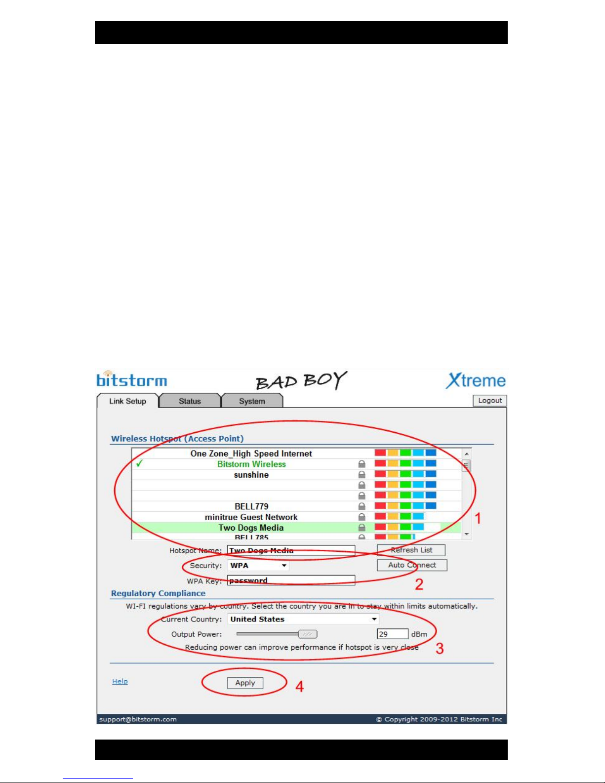
Refer to Fig 2. On the Link Setup tab, select a hotspot from the list or
enter an access point name into the Hotspot Name field [1]. Enter Wire-
less Security settings as required [2]. Select the country that you are in
[3]. Finish by clicking ‘Apply’ at the bottom [4]. A progress bar will ap-
pear at the top of the screen.
Xtreme remembers access Keys that are entered for secure hotspots.
By selecting a hotspot from the list, any previously entered Key will be
retrieved. Any changes made to the Key value will be remembered. A
Forget Hotspot button allows a remembered Key to be removed.
Note: With the Auto Connect button, Xtreme will automatically
connect to the strongest unsecured Access Point (hotspot) that it finds.
Keep in mind that the strongest signal may not be your best internet
connection choice.
Note: Hotspots generally announce themselves typically every two
minutes. Pressing Refresh List will add those hotspots that have an-
nounced themselves since the list was first populated.
Fig 2

Bitstorm Inc. Bad Boy Xtreme
10 www.bitstorm.com
Step 4
When Apply has completed, the Status tab will be displayed. Connec-
tion progress will be reported. You may see status of ’Connecting’,
‘Authenticating’, ‘Obtaining IP Address’, etc. See Fig 3.
Note: If connecting to an unsecured hotspot, additional authenti-
cation after connection may be required by the hotspot. To test for this
after connecting to the hotspot, simply try to open a web page and see
whether an additional authentication is presented by the hotspot. That
page may include a request for payment for internet access.
Note: On the System tab, backups of the Keys database can be
made. It is recommended to do this prior to using the Reboot or Reset
to Defaults buttons since using these features will erase any previous
remembered values. The restore feature allows backup Key values to
be reloaded into Xtreme. This ability to backup and restore is also
handy when moving Keys to another Xtreme or Express.
Este manual sirve para los siguientes modelos
3
Tabla de contenidos
Manuales populares de Antena de otras marcas

Alfa Network
Alfa Network APA-L01 Manual de usuario

Naval
Naval PR-422CA Manual de usuario

Feig Electronic
Feig Electronic ID ISC.ANTH200/200 Series Manual de usuario

TERK Technologies
TERK Technologies TV44 Manual de usuario

Directive Systems & Engineering
Directive Systems & Engineering DSE2324LYRMK Manual de usuario

HP
HP J8999A Manual de usuario