Visit BETE.com for comprehensive spray nozzle tools, case studies and literature.
413.772.0846 sales@bete.com
1
TROUBLESHOOTING:
BETE XA NOZZLES
XA COMPONENTS
BETE XA nozzles consist of a body, a spray
set-up, hardware assemblies, and optional
mounting devices.
The body is the base
component. It contains the
connection ports for the
liquid and air supplies, a
connection for the spray
set-up, and may contain a
connection for a hardware
assembly.
The spray set-up consists of an air cap
and a uid cap. The air cap and uid cap
combination control the spray performance,
including ow rates and spray pattern.
Optional hardware assemblies allow
either shutoff or shutoff and clean-out of
the uid cap. Hardware assemblies may be
actuated manually (B, C, and D hardware)
or pneumatically (E or F hardware). Not all
bodies accept all hardware.
Mounting devices offer a method of holding
the nozzle in a xed location. They attach to
the uid cap.
Operation of the air cylinder of the E or F
hardware requires a minimum air pressure
of 30 psi to retract the rod. Failure to provide
sufcient air pressure is one of the most
frequent causes of poor nozzle performance.
The E or F hardware feature a built-in air
cylinder which allows liquid ow to be shut
off at the nozzle tip, resulting in precise,
intermittent application of liquid. When
air pressure is released a spring causes the
cylinder to return to the closed position.
For the F clean-out option, the pin pushes
accumulated material from the liquid orice
as it returns. The clean-out pin is not able
to remove material from the orices in the
air cap.
Standard seal materials limit the XA to use
at temperatures less than 400°F. Materials
allowing use at higher temperatures are
available by special request. All spray set-ups
t on all bodies. All spray set-ups may be
used with hardware, however the available
hardware is limited by the chosen body style.
The 00 and 03 bodies can accept all
hardware assemblies. Complete nozzle
assemblies initially sold with manual
The BETE XA series is a multi-component
air atomizing system. The XA system was
designed to allow the swift exchange and
replacement of caps, bodies and tips. The
system provides a wide range of spray
patterns and simplies maintenance. The XA
series assemblies may consist of anywhere
from 6 to 11 parts.
Please be certain to read all instructions
carefully before assembling or disassembling
the nozzle. Damage to these assemblies can
occur if these procedures are not followed.
OPEN
CLOSED
hardware (B, C, or D) may be upgraded in the
eld to automatic hardware (E or F).
The square 00 body with E or F hardware
requires two separate air lines and more
complex piping.
The 01 body features a consolidated air inlet
combining both the atomizing air and cylinder
air in a single line, resulting in simplied piping
layouts. The 01 body can be used only for
applications where the atomizing air pressure
is ABOVE 30 psi.
The 01 and 02 bodies simplify external air line
connections by xing the orientation of the air,
liquid and cylinder inlets.
The 01 and 02 bodies may only be used with the
E or F hardware.
The 02 body requires two separate air lines,
one to supply atomizing air and one to supply
operating air to the cylinder. The two air lines
allow the use of atomizing air at pressures both
BELOW and ABOVE 30 psi, while maintaining
the minimum 30 psi to the cylinder.
The 05, 06, 07, and 08 bodies do not accept any
hardware.
The XA10 and XA11 bodies have a built in
air-operated cylinder. This integral cylinder
provides a smaller prole for use where space
is limited.
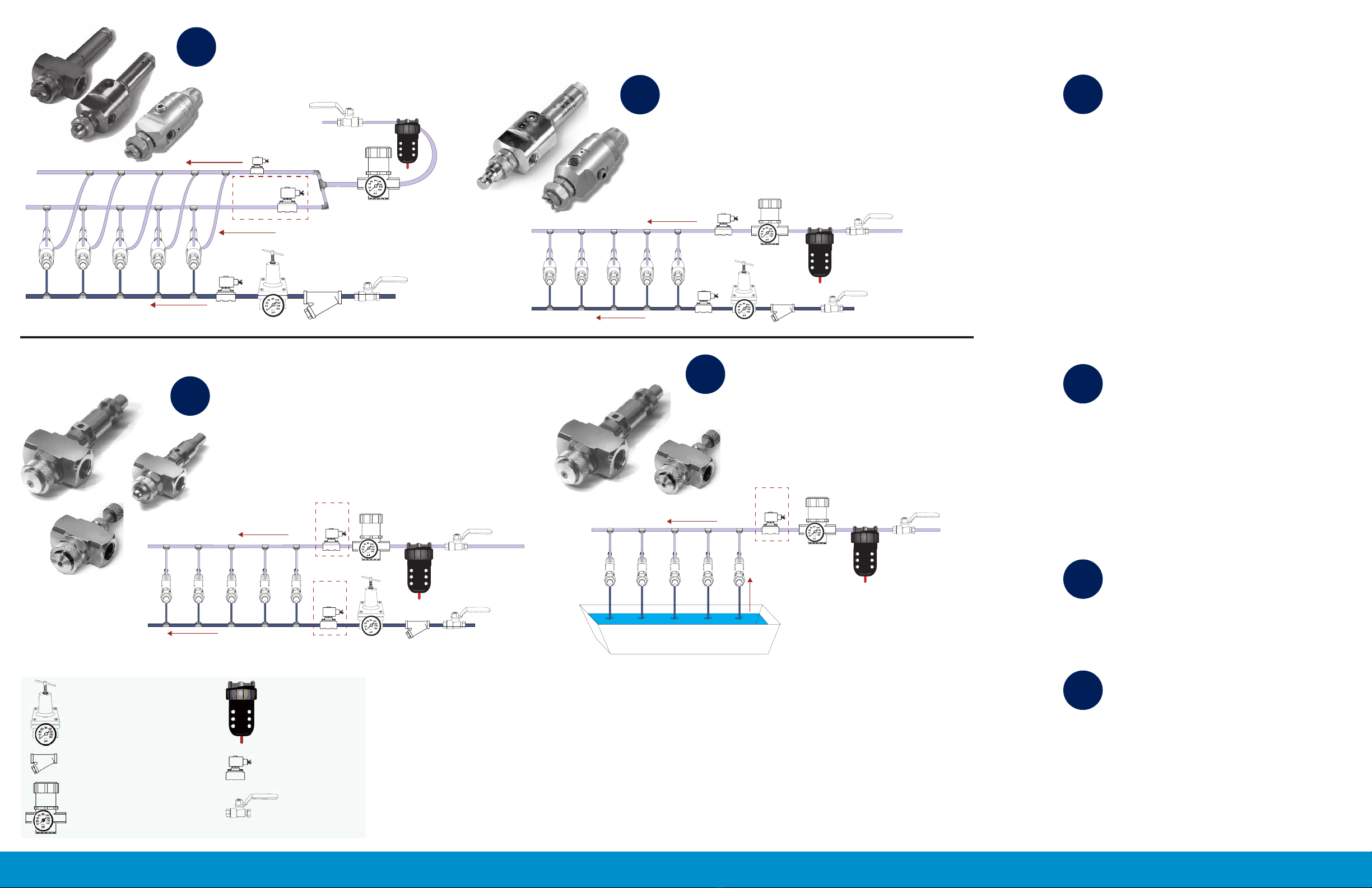
1. Adequately size air and liquid lines
to maintain required pressures at each
nozzle. (consult air and water ow charts
on page 4)
16. During installation, ensure the liquid
and air supplies are connected to the
correct port. The words “LIQUID” and
“AIR” are
stamped on
the bodies
adjacent to the
correct port.
4. To maintain adequate air pressure (30
psig min) for cylinder operation, use the
02 body if atomizing air pressure to the
nozzle is expected to fall below 30 psi.
2. Each siphon nozzle must have a
separate liquid feed line from the
reservoir.
9. To maintain atomization during
startup and shutdown, always turn on
air rst and turn off air last.
10. Multiple nozzle
installations are especially
sensitive to line sizes and
lengths. Size air and liquid
lines generously and avoid
large numbers of nozzles
(no more than 6) on a single
branch.
11. Humidication requires
high air/ liquid ratios,
usually in the range of 2 to
4 SCFM per gallon per hour,
to produce droplets small
enough for evaporation.
14. For viscosities greater
than 150 cP, consider using
one of the EF setups.
6. Flush out air and liquid lines before
connecting nozzles to clear out loose
material which could cause pluggage.
7. Install air and liquid pressure gauges
close to the nozzle location(s) to allow
accurate control of pressures.
3. For extreme temperatures and a range
of chemicals, consult chart of options for
special gaskets, sealants and Loctite®
adhesives.
8. As a general rule avoid spraying
counter-current to reduce contamination
problems from process environments.
12. Maximum operating rate for air
cylinders is 3 cycles per second.
Maximum pressure is 125 psi.
13. In dirty process environments, a
purge air pipe surrounding the nozzle
can reduce contamination problems.
15. Whenever ow rate accuracy is
critical, a positive displacement metering
pump or ow controller should be used.
5. For severe chemicals and abrasive
liquids, consult factory for optional
nozzle materials.
CAUTION
CAUTION
CAUTION
CAUTION
CAUTION
CAUTION
INSTALLATION TIPS