BENE IDEA Manual de usuario

https://build.bene.com/
FR INSTRUCTIONS DE MONTAGE ET D’UTILISATION
IDEA BOARD PACKAGE
EN ASSEMBLY AND OPERATING INSTRUCTIONS
IDEA BOARD PACKAGE
DE MONTAGE- UND BEDIENUNGSANLEITUNG
IDEA BOARD PACKAGE
22
FR
Conditionnement ............................. 3
Montage ......................................... 4
Câblage. 230 V ................................ 7
Montage. Ordinateur ........................ 8
Câblage. Haut-parleur / Caméra ......... 9
Montage. Haut-parleur / Caméra ...... 10
Montage ....................................... 11
Opération remarque.
Haut-parleurs externes ................... 12
Câblage. Ordinateur avec écran ....... 13
Montage ....................................... 14
Montage.
Écran sur FRAME_S Board ............. 15
Montage ....................................... 16
Montage
cache & opération remarque ........... 17
Aperçu des connexions ................... 18
Instructions d'entretien.
Certificats ..................................... 23
SOMMAIRE
EN
Included in delivery ......................... 3
Assembly ........................................ 4
Cabling. 230 V ................................ 7
Assembly. Computer ........................ 8
Cabling. Speakers / Camera ............... 9
Assembly. Speakers / Camera ........... 10
Assembly ...................................... 11
Operation note. external speakers.... 12
Cabling. Computer with display ....... 13
Assembly ...................................... 14
Assembly.
Screen on FRAME_S Board ............ 15
Assembly ...................................... 16
Assembly cover & start-up .............. 17
Overview connections ..................... 18
Cleaning instructions. Certificates ... 22
CONTENT
DE
Lieferzustand ....................................3
Montage ...........................................4
Verkabelung. 230 V ............................ 7
Montage. Rechner .............................8
Verkabelung. Lautsprecher / Kamera ..... 9
Montage. Lautsprecher / Kamera ........10
Montage .........................................11
Bedienungshinweis.
Externe Lautsprecher .......................12
Verkabelung.
Rechner mit Display ........................13
Montage .........................................14
Montage.
Screen auf FRAME_S Board .............15
Montage .........................................16
Montage
Abdeckung & Inbetriebnahme ...........17
Übersicht Anschlüsse .......................19
Pflegehinweise. Zertifikate ................21
INHALT

3
Montageanleitung
Montageanleitung
1
1
10
10 11 12
1
2
12
13
3
11
4
5
6
7
8
9
2
3
4
5
6
7
8
9
CONDITIONNEMENT
Cloisonnette
Cache
Screen (Taille d‘emballage 1736 x 1054 x 320 mm)
Connecteur & attaches
Conduite de câbles
Plateau de montage support mural TFT
Sandow décoratif
Rail
Socle
Cadre
Lecteur de signalisation numérique OPS Slot-In PC + Caméra + stylets
(Taille d‘emballage 430 x 310 x 26,5 mm)
(EN OPTION) HOYLU USB Port, HOYLU stylos, câble + clé de produit (A4)
Haut-parleur (Taille d‘emballage 1000 x 200 x 200 mm)
INCLUDED IN DELIVERY
Dividing wall
Cover profile
Screen (Packing size 1736 x 1054 x 320 mm)
Corner connectors & fittings
Wiring
Mounting plate for TFT wall-mounted bracket
Decorative elastic cord
Railing
Set of castors
Frame
OPS Slot-In PC + camera + pens (Packing size 430 x 310 x 26,5 mm)
(OPTIONAL) HOYLU USB Port, HOYLU pens, cable, product key (A4)
Speaker (Packing size 1000 x 200 x 200 mm)
LIEFERZUSTAND
Stellwand
Screen (Verpackungsgröße 1736 x 1054 x 320 mm)
Abdeckprofil
Lautsprecher (Verpackungsgröße 1000 x 200 x 200 mm)
Eckverbinder & Beschläge
OPS Rechner + Kamera + Stifte (Verpackungsgröße 430 x 310 x 26,5 mm)
(OPTIONAL) HOYLU USB Port, HOYLU Stifte, Kabel + Produktschlüssel (A4)
Rahmen
Rollenset
Reling
Dekogummiseil
Montageplatte für TFT-Wandhalterung
Kabelführung

4
1 2
3
MONTAGE
FRAME_S Board modele en H instruction de montage WP_MB283. Appuyez sur frein!
Fermoirs à pression
Bien centrer !
ASSEMBLY
FRAME_S Board H-Type assembly instruction WP_MB283. Use the castors brake!
Pressure locks
Position in the centre!
MONTAGE
FRAME_S Board H-Typ Montageanleitung WP_MB283. Rollenbremse betätigen!
Druckverschlüsse
Mittig positionieren!
5
45
USCH-VZ-FM6-DIN9021 8x
D990119
EJOT-PHPR-VZ-6/14 8x
D990457
MONTAGE
affleurant
Fermoirs à pression
La position doit être en haut à gauche!
Support mural CHIEF XSM1U : charge maximale au FRAME_S Board : 96 kg, au mur : 114 kg
ASSEMBLY
flush
Pressure locks
Position must be on top left!
CHIEF XSM1U wall-mounted bracket: maximum load on FRAME_S Board 96 kg, on wall 114 kg
MONTAGE
bündig
Druckverschlüsse
Position muss oben links sein!
CHIEF XSM1U Wandhalterung: maximale Belastung an FRAME_S Board 96 kg, an Wand 114 kg

6
7
SPAX-SKPZ-VZ-3,0*40 2x
D990150
6a 6b
MONTAGE
4x clipser du cache
Positionnnement multiprise & USB-Hub
USB-Hub (Option de HOYLU)
Fermoirs à pression
ASSEMBLY
4x clip the covering
Positioning connection plug board & USB-Hub
USB-Hub (Option of HOYLU)
Pressure locks
MONTAGE
4x Abdeckungen einklipsen
Positionierung Steckerleiste & USB-Hub
USB-Hub (Option von HOYLU)
Druckverschlüsse
230 V
310 mm
430 mm

7
CÂBLAGE. 230 V
Pour un câblage propre, utilisez des colliers de serrage et des serre-câbles!
GST18 câble branchement initial - Multiprise
Screen - Multiprise
Multiprise - USB Hub (avec Hoylu Bene Kit Display)
3x USB Hub - stylets numeriques
(avec Hoylu Bene Kit Display)
CABLING. 230 V
For clean wiring use cable ties and cable clips!
GST 18 starter cable - Connection plug board
Screen - Connection plug board
Connection plug board - USB Hub
(with Hoylu Bene Kit Display)
3x USB Hub - digital pens (with Hoylu Bene Kit Display)
VERKABELUNG. 230 V
Für saubere Verkabelung Kabelbinder und Kabelclips verwenden!
GST18 Anfangszuleitung - Steckerleiste
230 V
Screen - Steckerleiste
Steckerleiste - USB Hub (mit Hoylu Bene Kit Display)
3x USB Hub - digitale Stifte (mit Hoylu Bene Kit Display)

8
12
a
b
c
MONTAGE. ORDINATEUR
Mettez la ordinateur à la screen.
Retirez le cache.
visser 2 fois
ASSEMBLY. COMPUTER
Put the computer in the screen.
Remove the cover.
fasten with 2 screws
MONTAGE. RECHNER
Rechner in Screen stecken.
Abdeckung entfernen.
2x verschrauben

9
CÂBLAGE. HAUT-PARLEUR / CAMÉRA
Caméra - OrdinateurHaut-parleurs externes - Screen
CABLING. SPEAKERS / CAMERA
Camera - ComputerExternal speakers - Screen
VERKABELUNG. LAUTSPRECHER / KAMERA
Kamera - RechnerLautsprecher - Screen

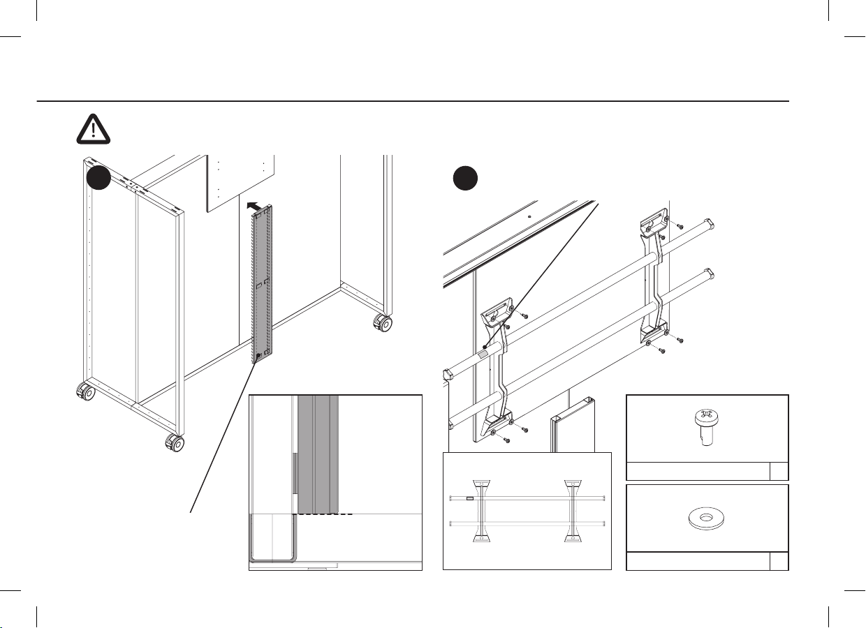
10
9 10 11 12
MONTAGE. HAUT-PARLEUR / CAMÉRA
Montage haut-parleur (6x vis). Premier angle aux haut-
parleurs puis à la screen. Pour les longueurs de câble, utilisez
les colliers de serrage fournis.
Montage caméra
Installation dans le haut-parleur gauche vu de l’avant.
Câble avec boucle pour la mobilité.
Longueur excédentaire
ASSEMBLY. SPEAKERS / CAMERA
Speaker assembly (6x screws).
First angle to speakers then to screen.
For cable lengths, use the enclosed cable ties.
Camera assembly
Installation in the left speaker seen from the front.
Cable with loop for movement.
Extra length
MONTAGE. LAUTSPRECHER / KAMERA
Lautsprecher Montage (6x Schrauben). Zuerst Winkel an
Lautsprecher dann an Screen. Für Kabelüberlängen sind die
beiliegenden Kabelbinder zu verwenden.
Kamera Montage
Einbau in den linken Lautsprecher von vorne gesehen.
Kabel mit Schlaufe für Beweglichkeit.
Überlänge
Otros manuales para IDEA
1
Tabla de contenidos


