Beacon FANAWAY MONTCLAIR Manual de usuario

V1.0 EU (05/2021)
FANAWAY MONTCLAIR
CEILING FAN
•INSTALLATION
•OPERATION
•MAINTENANCE
•WARRANTY INFORMATION
CAUTION
READ INSTRUCTIONS CAREFULLY FOR SAFE
INSTALLATION AND FAN OPERATION.
Fanaway Montclair Installation Instructions
1 | P a g e
CONTENTS
GB
Installation instruction manual .......................................................................................... 2
D
Installationsanleitung ........................................................................................................ 14
F
Guide d’installation............................................................................................................ 27
E
Manual de instrucciones de instalación............................................................................. 40
I
Manuale delle istruzioni di installazione............................................................................. 53
NL
Installatiehandleiding.......................................................................................................... 66
EL
Εγχειρίδιο οδηγιών εγκατάστασης ..................................................................................... 79
Contact:
Beacon International Ltd
Hong Kong Head Office: Room 05, 18/F, Kimberland Center, 55 Wing Hong Street, Cheung Sha Wan Kowloon, Hong Kong
Tel +852 34915904 Fax +852 34915917
China showroom / Office: 11/Fl, Guzhen Lighting Building B, Mid Zhongxing Road, Guzhen, Zhongshan, GuangDong, China.
Tel: +86 760 8986 6388 Fax: +86 760 8986 6380
www.beaconinternational.com
Beacon Lighting Europe GmbH
Campus Fichtenhain 42, 47807 Krefeld, Germany
TEL +49 (2151) 325 82 39 FAX +49 (2151) 325 70 65
www.beaconlighting.eu

Fanaway Montclair Installation Instructions
2 | P a g e
THANK YOU FOR PURCHASING
Thank you for purchasing this quality Fanaway product. To ensure correct function and safety, please read
and follow all instructions carefully before assembly, installation and use of this ceiling fan. Please keep
instructions for future reference.
SAFETY PRECAUTIONS
1. This appliance can be used by children aged from 8 years and above and persons with reduced physical,
sensory or mental capabilities or lack of experience and knowledge if they have been given supervision
or instruction concerning the use of the appliance in a safe way and understand the hazards involved.
Cleaning and maintenance shall not be undertaken by children without supervision.
2. Children should be supervised to ensure that they do not play with the appliance.
3. An all-pole disconnection switch must be incorporated into the fixed wiring, in accordance with local wiring
rules.
4. Do not dispose of electrical appliances as unsorted municipal waste, use separate collection facilities.
Contact your local government for information regarding the collection systems available. If electrical
appliances are disposed of in landfills or dumps, hazardous substances can leak into the ground water
and get into the food chain, damaging your health and well-being.
5. The structure to which the fan is to be mounted must be capable of supporting a weight of 48kg.
6. The fan should be mounted so that the blades are at least 2.3 m above the floor
7. This fan is suitable for indoor use only. Mounting the fan in a location where it is subject to water or
moisture is dangerous and may increase the risk of damage, injury or electrical shock and will void the
warranty.
8. Electrical installation should be performed by a qualified licensed electrician.
9. WARNING: If unusual wobbling or oscillating movement is observed, immediately stop using the ceiling
fan and contact the manufacturer, its service agent or suitably qualified persons.
10. The replacement of parts of the safety suspension system device shall be performed by the manufacturer,
its service agent or suitably qualified persons.
11. The fixing means for attachment to the ceiling such as hooks or other devices shall be fixed with a
sufficient strength to withstand 4 times the weight of the ceiling fan; that the mounting of the suspension
system shall be performed by the manufacturer, its service agent or suitably qualified persons.
Fanaway Montclair Installation Instructions
3 | P a g e
PARTS LIST
•Unpack your ceiling fan carefully. Remove all parts and hardware.
•Lay out all the components on a smooth surface and make sure there are no components missing before
assembling. If parts are missing, return the complete product to the place of purchase for inspection or
replacement.
•Check whether the ceiling fan has been damaged during transport. Do not operate/install any product
which appears damaged in any way. Return the complete product to the place of purchase for inspection,
repair or replacement.
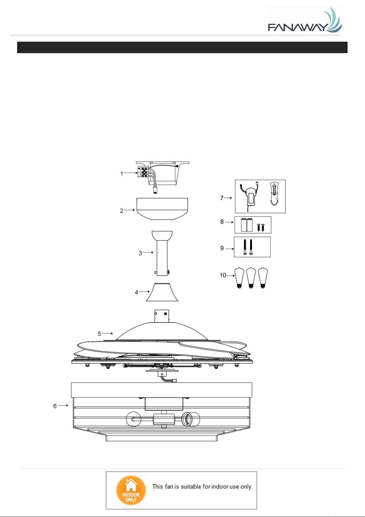
•Examine all parts, you should have the following list and Fig.1:
Fig. 1
Fanaway Montclair Installation Instructions
4 | P a g e
1
Mounting bracket x 1
6
Lamp base and shade x 1
2
Canopy x 1
7
Receiver & Remote x 1 Set
3
Down rod with ball joint x 1
8
Battery x 2 & screw x2
4
Bolt and pin cover x 1
9
Mounting screws x 2
5
Fan assembly x 1
10
Globes x 3
INSTALLING THE MOUNTING BRACKET
•The ceiling fan must be installed in a location so that the blades are spaced 300mm from the tip of the
blade to the nearest objects or walls.
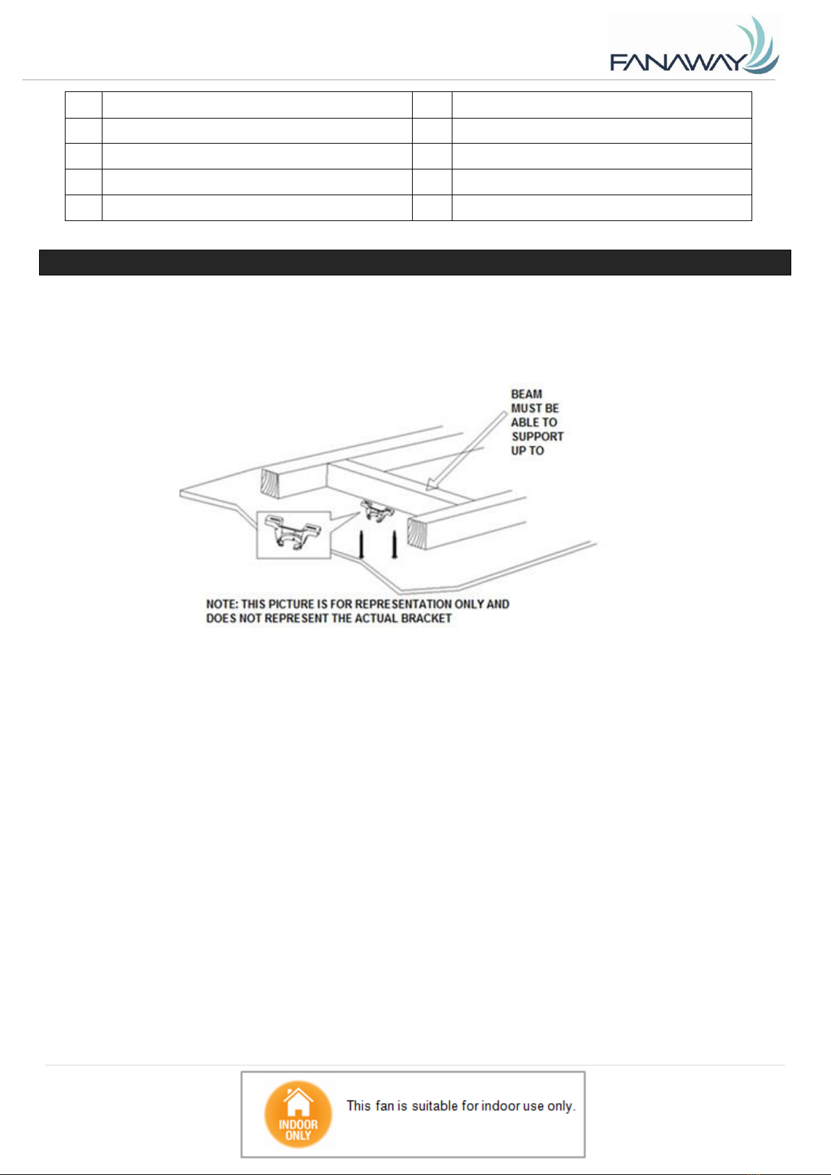
•Install the hanging bracket to the ceiling joist or structure that is capable of carrying a load of at least 48kg,
with two long screws provided. Ensure at least 30mm of the screw is threaded into the support. (Fig. 2)
NOTE: The bracket screws provided are for use with wooden structures only. For structures other
than wood, the appropriate screw type MUST be used. Ensure the screws used are suitable for the
mounting surface and the surrounding environment.
Fig. 2
48 KG
Fanaway Montclair Installation Instructions
5 | P a g e
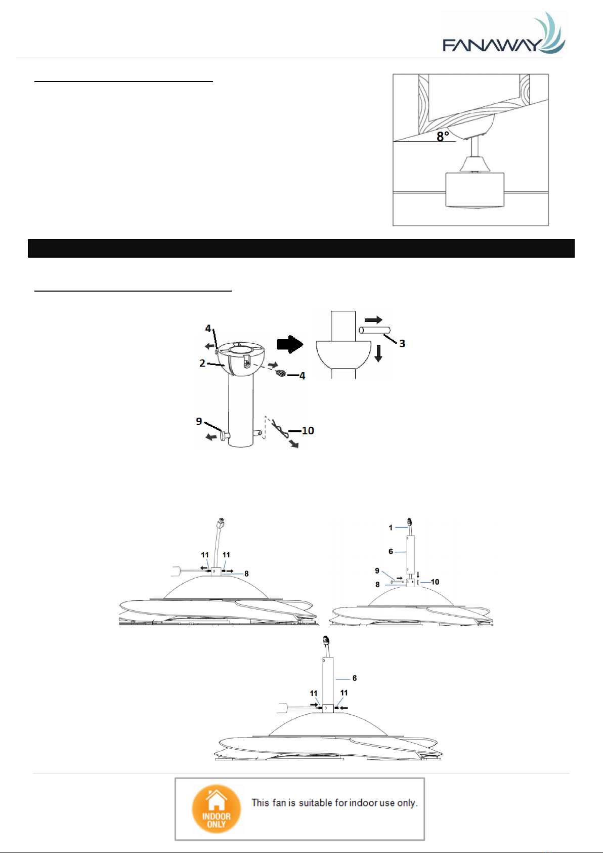
ANGLED CEILING INSTALLATION
This fan hanging system supports a maximum 8 degree angled ceiling
installation.
INSTALLING THE FAN
INSTALLING THE DOWN ROD (Fig. 4)
1. Remove the ball joint (2) and dowel pin (3) by loosening the set screws (4) from the down rod (6).
Remove the hitch pin (9) by removing the lock clip (10) (Fig. 4.1). NOTE: Do not discard keep these
parts, they are required to reassemble later.
Fig. 3
Fig. 4.1
Fig. 4.3
Fig. 4.4
Fig. 4.2

Fanaway Montclair Installation Instructions
6 | P a g e
2. Loosen the set screws (11) on the down rod coupling housing (8). (Fig. 4.2)
3. Carefully feed the fan wires (1) up through the down rod (6). (Fig. 4.3)
4. Assemble the down rod (6) into the down rod coupling housing (8), by inserting and line up the down rod
coupling housing holes with the down rod holes and insert the hitch pin (9) and secure with the lock clip (10).
(Fig. 4.3)
5. Secure the down rod (6) by tightening the set screws (11). (Fig. 4.4)
6. Insert the decorative cover (7) onto the down rod (6) to cover the down rod coupling housing (8).(Fig. 4.5)
7. Insert the canopy (5) over the down rod (6) and install the ball joint (2) and dowel pin (3) back onto the
down rod (6) and secure by tightening the set screws (4). (Fig. 4.5 and Fig. 4.6)
HANGING THE FAN
Lift the fan assembly onto the mounting bracket. Ensure the key slot (A) of the hanger ball is positioned on
the key pin (B) of the mounting bracket (C) to prevent the fan from rotating when in operation. (Fig. 5)
Fig. 5
Fig. 4.6
Fig. 4.5

Fanaway Montclair Installation Instructions
7 | P a g e
LIGHT KIT INSTALLATION
LIGHT KIT INSTALLATION (Fig. 6 & 7)
1. Loosen the screw (1) from the fan bracket. Align the two slot screws with the keyhole slots (2) of the light
kit bracket. (Fig. 6)
2. Turn the light kit counterclockwise until the slot screws are firmly at the end of the slots (2).
3. Secure screw (1) to the lamp shade bracket. Tighten all three screws. Do not over-tighten.
4. Connect the quick connector to the lamp holder part (3). (Fig. 7)
5. Secure the lamp-holder part (3) to the light kit bracket by tightening the 3 screws. Do not over-tighten.
6. Install globes (4) into the lamp holders. Do not exceed the maximum power rating.
Fig. 7
Fig. 6

Fanaway Montclair Installation Instructions
8 | P a g e
ELECTRICAL WIRING DIAGRAM THE FAN
WARNING: FOR YOUR SAFETY,Electrical installation should be performed by a qualified licensed
electrician.
NOTE: AN ADDITIONAL ALL POLE DISCONNECTION SWITCH MUST BE INCLUDED IN THE FIXED
WIRING.
From mains supply to mounting bracket terminal block: (Fig. 8)
1. Connect the live supply wire to the “L” terminal of the terminal block on the mounting bracket.
2. Connect the neutral supply wire to “N” terminal of the terminal block on the mounting bracket.
3. Connect earth wire to the “” earth terminal of the terminal block on the mounting bracket.
From mounting bracket to receiver and fan motor : (Fig. 8)
Connect the supply wiring quick connector from the mounting bracket to the input quick connector of the fan
receiver . (Fig. 8)
Connect the output wires quick connector of fan receiver to the input wires quick connector of the fan
assembly. (Fig. 8)
Fig. 8
Fanaway Montclair Installation Instructions
9 | P a g e
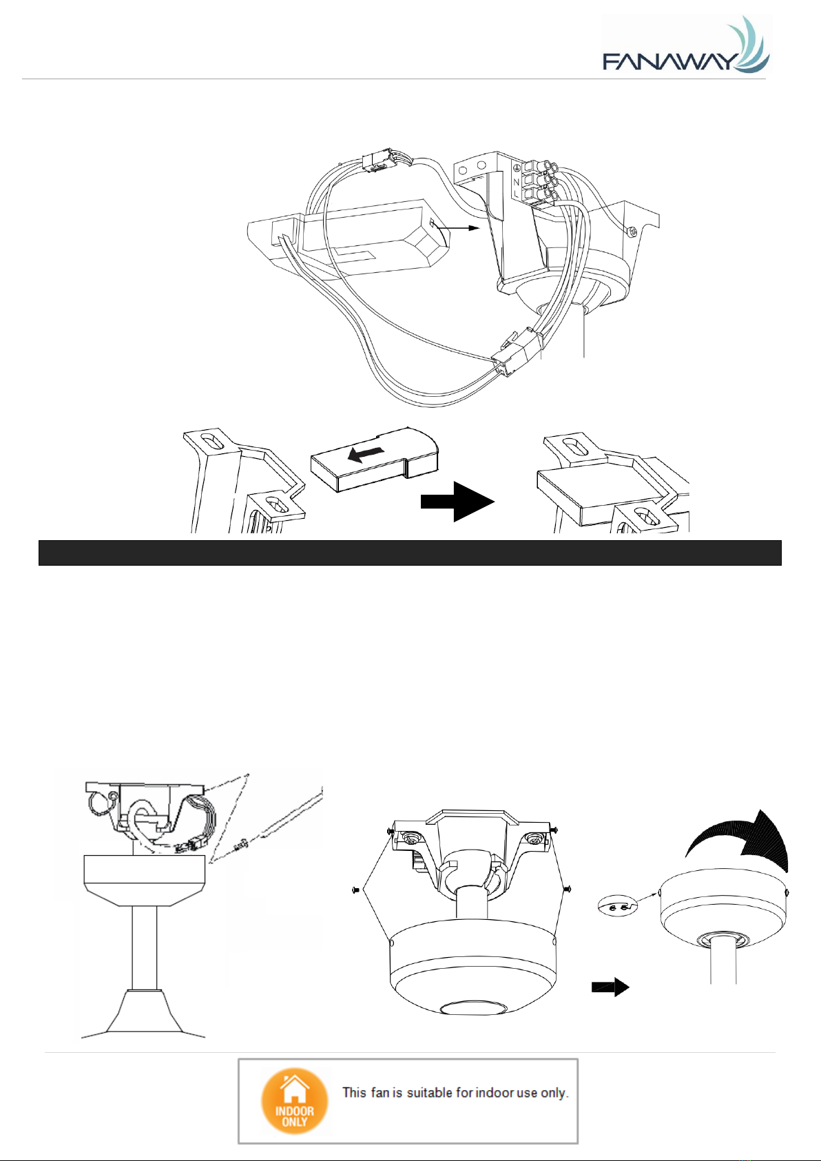
•Carefully insert the Remote Receiver above the hanger ball in the remainder spacing in the mounting
bracket. Take care not to damage or loosen any of the wiring. (Fig. 9).
FINISHING THE INSTALLATION
•After completing the electrical connection at the mounting bracket terminal block, connect the ceiling fan
wiring via the quick connector plug.
•Ensure the earth wiring is secure and correct, by performing an earthing continuity test from the fan’s
accessible metal body and lamp base back to the earth terminal at the terminal block on the mounting
bracket.
•Cover the mounting bracket with the canopy. Ensure all electrical wiring is tucked inside the canopy and
that the wires are not damaged during this step. Secure the canopy to the hanger bracket using the screws
provided. (Fig. 10)
Fig. 10
Fig. 9
Tabla de contenidos
Idiomas:
Otros manuales de Admirador de Beacon


