BDS RD-3151 Manual de usuario

Service Manual
RD-3151
Rear Delivery Dr. Assistant with
Swivel Bar
Rev 3 - 6-17-19 900-105

800.237.2303 ◆503.538.8756 ◆503.538.2845 Fax ◆www.beaverstatedental.com 1
RD-3151
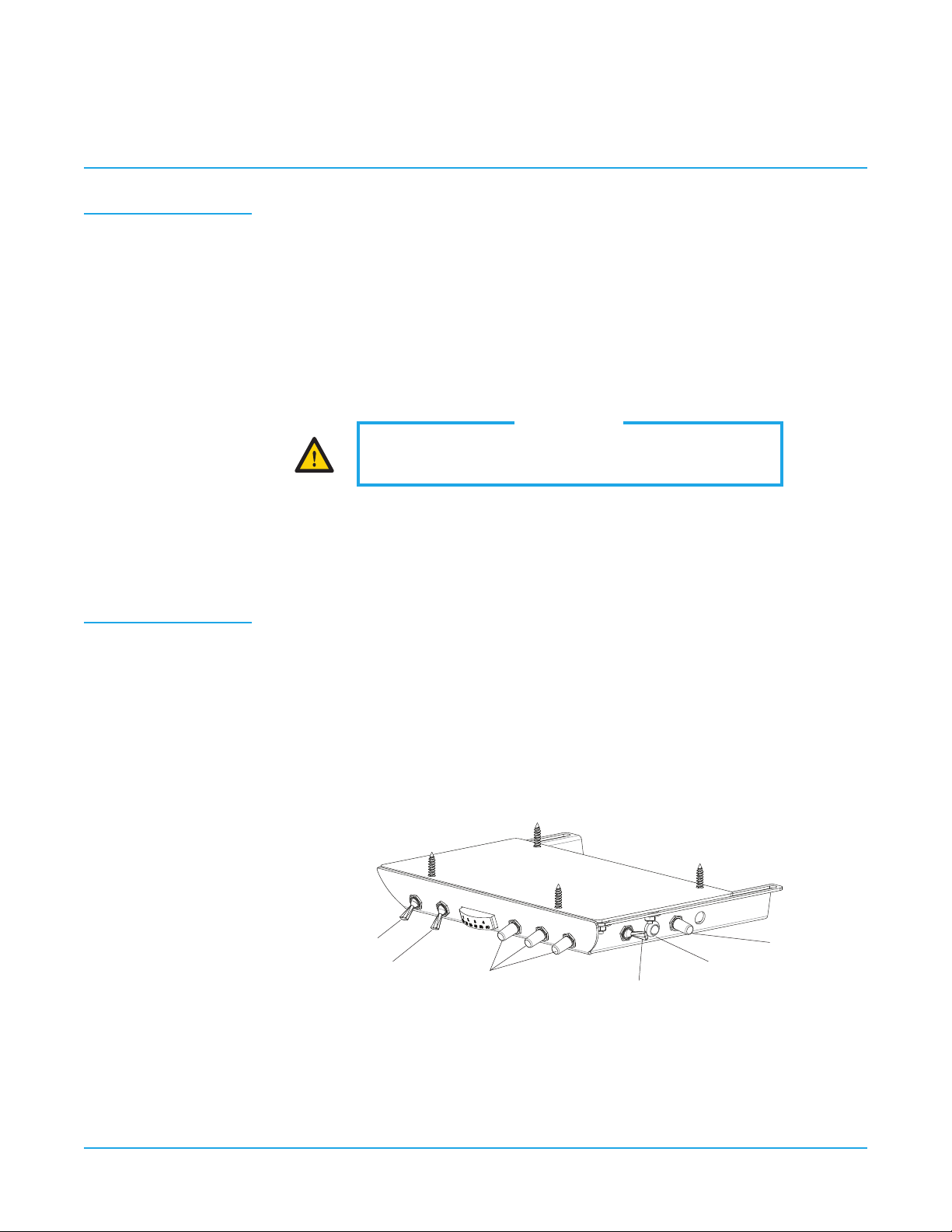
Installation Under Cabinet Mount
1. Place the shipping carton in the desired location. Remove the unit from the shipping
carton.
2. Remove the full sized mounting template from the service manual. Place in desired
location and mark four places to be drilled. We recommend the faceplate to be offset
inward 1/8" from the front of the counters edge.
3. Pre-drill a hole 1/2" deep using a 5/32" drill bit. Do not drill through the counter top
4. Slidetheunitapartbyseperatingthefaceplateassemblyfromthexedbodyas-
sembly.Withtheunitfullyextended,lineuptheouterchassisaligningtheholeswith
thepre-drilledholes.Placea1/4"HexScrewinonecornertolightlyfastenitusinga
3/8"HexDrive.Repeattheprocessuntilallfourscrewsareinstalled.Tightensecurly
making sure the face plate slides in and out freely.
5. Inserttheumbilicaltubinginrstandfollowwiththeunit.
6. Mount the holder bar with holders in desired location under counter top.
7. Installoptionalmastervalveassemblies,withlterandregulator,ontothemanual
shut-offvalves.(Pressuresarepresetatthefactory:80psiair,40psiwater).
8. Connect the supply tubings to the appropriate air and water supply lines.
Checkairpressure,adjustto80psiifnecessary.
Checkwaterpressure,adjustto40psiifnecessary.
Testhandpiecesforproperfunction.
Testsyringeforproperpressureandfunction.
Final
Adjustments
NOTE
This unit requires a regulated air and water supply.
Filters are highly recommended.
800.237.2303 ◆503.538.8756 ◆503.538.2845 Fax ◆www.beaverstatedental.com
2
RD-3151
Operation 1. Turnonthemasterswitchlocatedontherightsideofthefaceplate.
2. Thehandpieceisautomaticallyactivatedwhenliftedfromtheholder.
3. Depress the foot control to activate each handpiece. Pressure is shown on the gauge for
the handpiece being used.
4. Individual handpiece pressure adjustments are located on the autoblock inside the
unit.Toadjustthepressuretoeachhandpiece:
a. Turnadjustmentscrewclockwise to decrease the handpiece pressure.
b. Turnadjustmentscrewcounter-clockwise to increase the handpiece pressure.
5. Handpiece coolant water can be turned on or off with the toggle switch located in the
lower center of the faceplate.
6. Watercoolantowadjustmentislocatedtotherightofthewatercoolanttoggleswitch.
Thepurgeswitchushesfreshwaterthroughthewatercoolantsystem.Guidelinesfromthe
CenterforDiseaseControl(CDC)recommendsthateachhandpiecebeushed(purged)20to
30 seconds between patients and several minutes at the beginning of each day. Handpieces
must be removed from the holder to activate the purge system.
CAUTION
Whenadjustingthehandpiecepressure,donotover-
tighten the screws. Damage may result.
Control Panel RD-3151
Handpiece Purge
Handpiece Water
Flow Control Knobs
Purge
ToggleSwitch
Master Switch
Air Coolant
Water On/Off
Indicator

800.237.2303 ◆503.538.8756 ◆503.538.2845 Fax ◆www.beaverstatedental.com 3
Troubleshooting
Symptom
Possible Causes
Symptom
Possible Causes
Symptom
Possible Causes
Handpiece lacks power.
A. Impropersupplypressurefromcompressor(80psi).
B. Checkhandpiecepressureadjustmentonunit.
C. Airltermaybeplugged.
D. Pinched supply tubing.
E. Defectivehandpiecegasketatconnectionwithtubing.
F. Defective handpiece.
Water coolant does not shut off when foot control is released.
A. Adjustairpressureto80psi—waterpressureto40psi.
B. Footcontrolisnotexhausting.
C. Defective water relay valve.
More than one handpiece is operating.
A. Handpiece is not all the way in the holder.
B. Improperadjustmentonpilotvalveinthehandpieceholder.
C. Defective shuttle valve to gauge.
Insufcientwatercoolant.
A. Adjustcoolantowvalve.
B. Waterltermaybeplugged.
C. Handpiece may be plugged.
D. Pinched supply tubing.
E. Improperadjustmentofwaterrelayvalve
Water coolant is running from handpiece while in the holder.
A. Water pressure too high.
B. Air pressure too low.
C. Handpieceholderoutofadjustment.
Water coolant is running continuously.
A. Purgeswitchison(onapplicablesystems).
B. Water pressure to high.
C. Handpieceholderoutofadjustment.
D. Defective water relay valve.
Symptom
Possible Causes
Symptom
Possible Causes
Symptom
Possible Causes
44
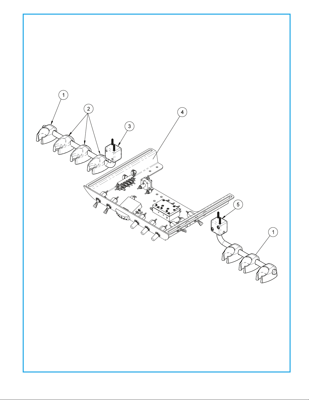
REAR DELIVERY DR. ASSISTANT SWIVEL BAR
RD-3151
ITEM
1
2
3
4
5
PART DESCRIPTION
Syringe Holder. .......................................
Auto Holder.............................................
Pivoting Holder Bar 10 -1/2”..............
Rear Deliver Unit Head........................
Cabinet/Wall Holder Bar 8“................
PART NUMBER
141-100
122-100
105-177
3100-RD
105-170
QTY
4
3
1
1
1

55 REAR DELIVERY UNIT HEAD ASSEMBLY
3100-RD
ITEM
1
2
3
4
5
6
7
8
9
10
11
12
13
14
15
16
17
PART DESCRIPTION
4-40 Hex Nut ...........................................
Washer, No. 6 ...........................................
1/2”Plug....................................................
Shuttle Valve............................................
Manifold....................................................
Rectangular Gauge...............................
Pneumatic Indicator.............................
Chassi.........................................................
3 Way Momentary Toggle Valve.......
3 Way Toggle Valve ...............................
3 Way Toggle Valve................................
Needle Flow Valve. ................................
Water Relay Valve ..................................
Autoblock.................................................
Screw, 18-8 ...............................................
Washer, 0625 OD x .199.......................
Spacer, A-Series ......................................
PART NUMBER
002-017
003-032
010-013
014-012
023-003
026-003
026-020
103-330
120-005
120-007
120-000
121-000
123-000
125-030
001-270
003-070
103-334
QTY
2
2
3
1
1
1
1
1
1
1
2
3
1
1
4
4
4

66
Water Relay Valve 123-000
ITEM
1
2
3
4
5
6
7
8
9
PART DESCRIPTION
Molded Body....................................
Molded Clip.......................................
Pin, 1/16" x 5/16".............................
Handpiece Actuator Lever...........
Screw, 4 x 1/2" ..................................
Screw, 8 x 1/2" ..................................
Washer Tray Mount Spacer.........
Automatic Holder Valve................
Set Screw, 6-32 x 3/16"..................
PART NUMBER
122-101
122-102
009-010
122-103
001-019
001-018
003-004
122-031
005-019
QTY
1
1
1
1
2
2
1
1
1
AUTOMATIC HANDPIECE HOLDER
122-100
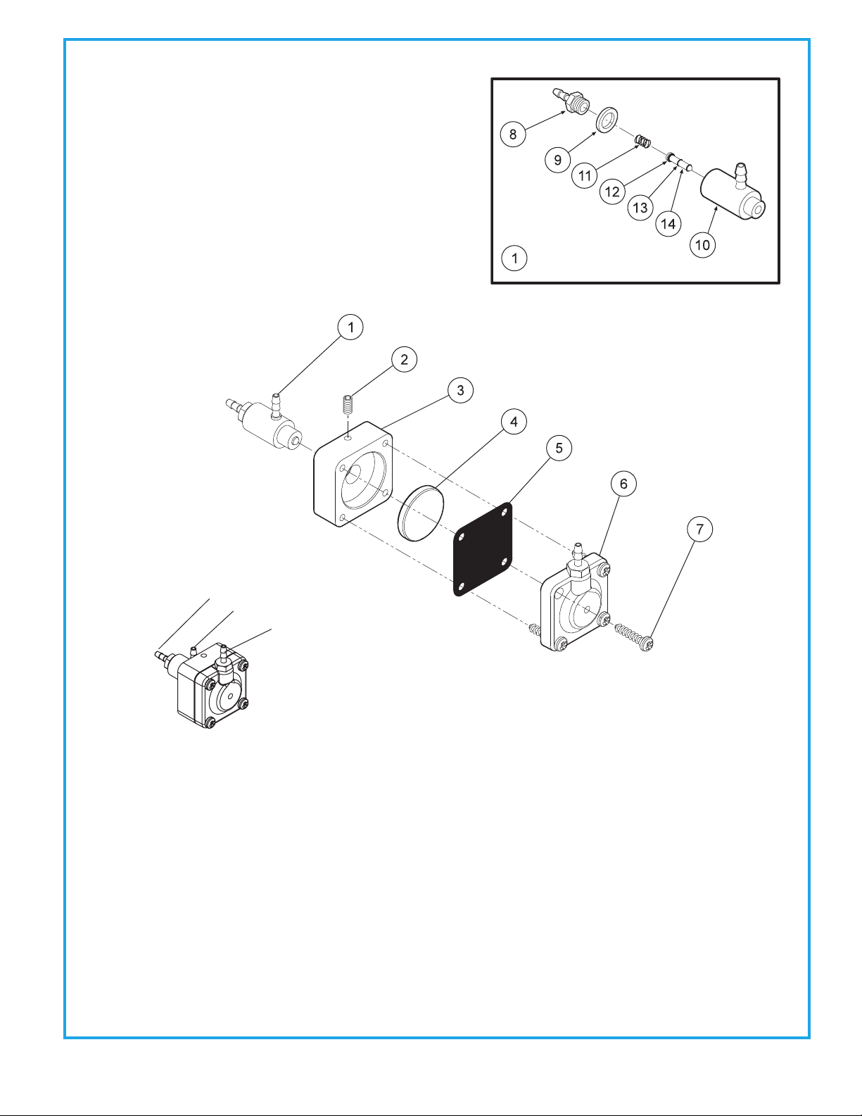
77 NON-RETRACTION WATER RELAY VALVE
123-000
ITEM
1
2
3
4
5
6
7
8
9
10
11
12
13
14
PART DESCRIPTION
Cartridge Body Assembly.............
Set Screw, 4-40 x 5/8".....................
Body....................................................
Piston..................................................
Diaphragm........................................
Cap.......................................................
Screw, #6 x 1/2"................................
Barb, 10-32 x 1/16".........................
Plastic Washer, 1/4"........................
Valve Body..........................................
Spring.................................................
O-Ring, 002.......................................
O-Ring, 001......................................
Stem...................................................
PART NUMBER
123-018
005-028
123-013
123-014
127-031
123-012
001-267
022-009
003-001
123-017
008-011
017-502
017-501
123-015
QTY
1
1
1
1
1
1
4
1
1
1
1
1
2
1
Water Relay Valve 123-000
Air In
Water In
Water Out

88
AUTOMATIC HANDPIECE CONTROL BLOCK
125-030
ITEM
1
2
3
4
5
6
7
8
9
10
11
PART DESCRIPTION
Adjusting Stem................................
O-Ring, 021........................................
Screw, 6-32 x 1/4"...........................
Cap.......................................................
Plastic Washer, 8-32 x 1/16"........
Barb, 8-32 x 1/16"...........................
Diaphragm........................................
Body....................................................
Barb, 10-32 x 1/16"............................
Barb, 10-32 x 1/8"...........................
Plastic Washer, 1/4"........................
PART NUMBER
125-023
017-021
001-131
125-032
003-030
022-040
125-016
125-031
022-009
022-010
003-001
QTY
3
3
7
1
3
3
1
1
9
4
13
Drive Air In
OuttoGauge
Coolant Air In
Coolant Water In
Coolant Water Out
Drive Air Out
Coolant Air Out
Signal Air In
Handpiece Pressure
Adjustment
Theautomaticcontrolblockisthecontrolcenterforyourdentalunit.
Individualhandpiecepressureadjustmentsarelocatedonthe
autoblock.Toadjustthepressuretoeachhandpiece:
a. Turnadjustmentscrewclockwisetodecreasethe
handpiece pressure.
b. Turnadjustmentscrewcounter-clockwisetoincrease
the handpiece pressure.
CAUTION
When adjusting the handpiece
pressure,donotover-tightenthe
screws. Damage may result.
99
Drive Air In
OuttoGauge
Coolant Air In
Coolant Water In
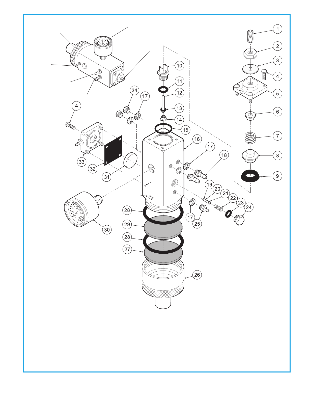
MASTER VALVE
127-010-AIR
Batch Stamp
Located Here
Vent Hole
ITEM
1
2
3
4
5
6
7
8
9
10
11
12
PART DESCRIPTION
Set Screw, 1/4-20 x 5/8”.........................
Jam Nut, 1/4-20.......................................
Washer........................................................
Screw, 6-32 x 3/8”....................................
Cap...............................................................
Spring Seat...............................................
Spring.........................................................
Cup Seat.....................................................
Cup Seal......................................................
Seat..............................................................
O-Ring, 008................................................
Stem.............................................................
PART NUMBER
005-024
002-006
003-015
001-041
127-033
127-043
008-008
127-044
017-200
127-026
017-008
127-024
ITEM
13
14
15
16
17
18
19
20
21
22
23
ITEM
24
25
26
27
28
29
30
31
32
33
34
PART DESCRIPTION
O-Ring, 004........................................
Spring..................................................
O-Ring.................................................
Body.....................................................
Plastic Washer, 1/4”........................
Barb, 10-32 x 1/8”............................
O-Ring, 001........................................
Stem....................................................
O-Ring, 003........................................
Spring..................................................
O-Ring, 007.................................. .....
PART DESCRIPTION
Plug...................................................................
Barb, 10-32 x 1/16”......................................
Cap Inlet..........................................................
Filter Element, 100 Micron........................
O-Ring, 018.....................................................
Filter Element, 35 Micron..........................
Gauge...............................................................
Piston................................................................
Gasket..............................................................
Cap....................................................................
Plug...................................................................
PART NUMBER
017-504
008-028
017-018
127-040
003-001
022-010
017-501
127-045
017-103
008-040
017-007
PART NUMBER
020-026
022-009
127-041
119-005
017-022
119-004
026-001
123-014
127-031
123-030
001-001
QTY
1
1
1
8
1
1
2
1
4
3
2
1
QTY
1
1
1
1
5
2
2
1
1
1
1
QTY
1
1
1
1
2
1
1
1
1
1
2
Constant Air Out
Out to Foot Control
ToMaster
On/Off Switch
Regulator Pressure
Adjustment
PressureGauge
Air—80lbspsi
Water—40lbspsi
Remove Brass Knurled Cap
toReplaceFilterElement
Tabla de contenidos
Otros manuales de Equipo dental de BDS


Manuales populares de Equipo dental de otras marcas

Vatech
Vatech EzRay Air VEX-P300 Manual de usuario

KaVo
KaVo GENTLEpower LUX Contra-angle 25 LP Manual de usuario

DENTSPLY
DENTSPLY SmartLite Focus Manual de usuario

LM
LM ProPower CombiLED Manual de usuario

Owandy Radiology
Owandy Radiology RX-AC Manual de usuario

mectron
mectron Piezosurgery Manual de usuario


