
BAGNODESIGN BAGNOSPA BDD-SPA-GEN3-1-A Manual de usuario

BDD-SPA-GEN3-1-A
BAGNOSPA STEAM GENERATOR 3KW 220V50HZ WITH DIGITAL CONTROL PANEL,
BLUETOOTH MUSIC BOX, 2X SPEAKERS, WIFI BOX AND 4 RGB LIGHTS
www.sanipexgroup.com

GEN3-1
Cataloge
Prologue------------------------------------------------------------------------------1
Users instruction---------------------------------------------------------------------1
The selection of the place of the steam equipment installation-------------------1
The typical illustration of the steam equipment installation-----------------------2
Installation of the tube---------------------------------------------------------------3
Drawing of the steam generator----------------------------------------------------5
Electric requirements----------------------------------------------------------------6
Power line assemble illustration-----------------------------------------------------8
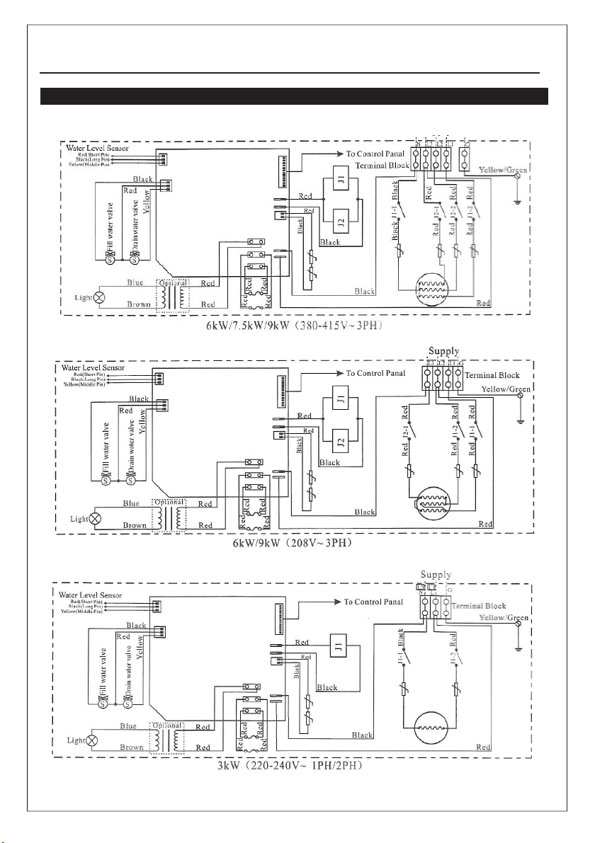
Wiring Diagram 380-415V(3PH)----------------------------------------------------9
Wiring Diagram 208V(3PH) --------------------------------------------------------10
Wiring Diagram 220-240V(1PH/2PH)----------------------------------------------11
Installation of the top light----------------------------------------------------------12
Choose your models-----------------------------------------------------------------13
Maintenance of the stream generator----------------------------------------------13
Steam generator structure drawing------------------------------------------------14
Usual malfunction and resolve------------------------------------------------------15
Specification-------------------------------------------------------------------------16

!
GEN3-1
Users instruction
!
We are not responsible for the malfunction and damage came from the installation
that not comply to the users manual.
1. Make sure the model and the accessories are correct, include the voltage input.
2. Make sure the steam power are matched with the sauna room' dimension. Pay much
attention to the steam room's cubage and construction. If you have any problem, please
refer to the Page 11 about the dimension selection.
3. Make sure to read this manual carefully for the secure and effective use.
4. We shall not be responsible for the product damage or malfunction caused by self-
installation or the operation procedures which is not operated by the users instructions.
5. GS08M series are packaged with a case, please check the goods when it arrived to assure it
is in good condition, if you find any damage in the package, please contact the
transportation company or the supplier to claim for compensation.
6. This product must be used indoor.
Install an exhaust fan outside of the steam room in case that it can expel the
excessive steam from the shower room.
Some locations recommended to customers for the right installation.
1.The distance to the steam room less than 6m, the standard pipe which link the controller and
the steam generator should be 6.5m.
2.The steam generator should not be installed in the steam room
3.Not installed outdoor or in any places that will influence the security of the machine by the
environment.
4.Do not install it in the frigid loft or any places the water will freeze.
5.Do not install it near the burnable and caustic object or chemical(coal gas or dope
thinner etc.)
6.Installed in a dry place and the ventilation is good.
Choosing a right location
Welcome to use GEN3-1 series stream generator,this series contains a steam
furnace and a controller. You can adjust the temperature of the sauna room and set the
working time of the steam as you wish. And the system contains a overheat/dry-
burnt protection system and a security valve could prevent the
overheating and assure the steam furnace working at a regular air pressure. It has the
reasonable design and working very stable,very convenient to install, healthy
and comfortable,is the top grade sauna equipment for the modern family,
hotel,restaurant,meeting place and the clubhouse will be satisfied with the noticeable
effects on pain relief,weight control,skin stimulation and stress reduction due
to an increased blood circulation got from steam bath.
GS08A serie s in clued 9 t ypes o f machin es that output power vari es
in 3kW, 4.5kW, 6kw, 9kw,the users could choose it according to their requirements.
Prologue
Important:

!
GEN3-1
7. Stable and horizontal.The steam generator has a hanging groove for immobility on wall. Make
sure the machine is steady and horizontally installed.
8. On both sides and the top of the steam generator need to reserve at least 12 inches space.
9. The place where the machine is installed must be easily cleaned up and convenient for the
disassembly of the machine.
10. The installation place must be convinent for the drain of water in inner pot.
11. The steam tube,safty valve, drain valve,water tube,steam outlet are still very heated after
the steam generator have stopped working for some time.Must take some measures for example
using the heat insulation tube to prevent the damage of the hot tube and keep the outlet
away from the people.
12. The controller must be installed in the steam room,please refer to the
chapterinstruction of the controller's installation and operation of the manual.
The steam generator(including the controller) are comply with the CE and UL
certificate, and are adaptive in the moisture environment.
!
Installation drawing of the steam generator
Attention:
The drawing is only for explanation.
As for practical design of steam
room, please consult with qualified
designer or architect.
Attention:

Installation of pipeline:
!
Warning: The installation of all the pipes should be operated by qualified plumbers with
corresponding operation certificate in accordanceance with national requirements:
1. Use joints when connecting pipes.
2. Use brass pipes or copper hoses only.
3. Do not use black and galvanized or PVC pipes.
Water supply pipe (1/2'')
1. Connect hot water or cold water pipes. It had better be hot water pipe with a temperature no
more than 70°C.
2. Install stop valve in the water supply pipe. The stop valve should be installed in a place where it is
easily operated in emergency.
3. Clean the water supply pipe completely before connecting the water pipe to the steam engine.
4. It is suggested that filter and anti-furring equipment in the water supply pipe.
5. The water pressure should be at best between 15 and 20 pounds/square inch. If necessary,
decrease the pressure accordingly.
6. If necessary, install equipment to prevent the water producing sound.
Steam pipe (4.5kW pipe size:1/2''; 6kw & above:3/4'')
1. Do not install any valves in the steam pipes. The steam can never be obstructed.
2. Install a brass steam pipe(4.5kW pipe size: 1/2''Ј6kw & above:3/4'') between the steam outlet
and the steam nozzle.
3. The heat insulation material used to insulate the steam pipe should be resistant to temperature as
high as 120°C or higher.
4. The horizontal part of the steam pipe should be installed inclining to the steam outlet or in the
direction of steam engine. Do not bend it in a hape to make sure that the cooled water will not
stay in the curved pipe of the steam pipe.
5. The shorter the steam pipe, the better. Try to decrease the number of elbows and avoid abrupt
turns.
!
Attention: Do not install the steam pipe in an upper or lower direction now and then, which will affect
the output of steam.
Steam nozzle (4.5kW pipe size: 1/2'' Ј6kw & above:3/4'')
!
Attention: Since the steam nozzle and steam outlet are very hot, try to avoid install the steam
nozzle in the position which will easily come into contact with the person in a bath in case the steam
should splash to scald the user.
1. Install the steam nozzle in the position 6-12 inches above the ground. If the steam bath is in the
bathtub or bathroom, install the steam nozzle 6 inches above the bathtub. If the steam room
above adopts materials like acryl or non-heat-resistant sheet, install additional heat insulator.
2. The steam spray outlet should be installed face down. Wind a few circles of green material belt
around the whorl of the steam pipe, install the steam nozzle and tighten with hands.
!
Attention: In order to protect the steam nozzle, do not use the spanner or other tools to tighten,
use a little soap water and soft sponge to wipe, and do not use erosive chemical solutions or crude
cleaning tool.

!
Important:
1. Please consult your distributors of building materials like acryl, fiber glass or other anti-heat
sheet about the installation position of steam nozzle.
2.
3. In the entire steam room, it is required that steam can not leak out. The pipes, its accessories
and the holes in the wall should be air proof by applying air proof glue so that no steam will
enter the holes in the wall.
If non-heat-resistant material like acrylic
is used as building material, reserve a gap
no smaller than 1/4'' and fill with
heat-insulated material.
Airproof green material belt
Use airproof silicon gel or
or r e s p o n d i n g a i r p r o o f
material to fill in the gaps in the
wall to achieve the water-proof
and damp-proof effect. Inside wall in the steam room
Drainpipe (1/2'')
According to national or local rules, the steam engine drainage valve should be equipped with drainpipe.
The steam engine drains the water by using weight.
!
Attention: The drainpipe should not incline upwards so as to facilitate the drainage of water.
Safety valve
1. Safety valve is a piece of safe equipment in order to prevent too much steam pressure in the
interior steam engine due to various reasons.
2. The pressure limit range of safety valve is 15 PSI and the pressure will begin to decrease if
pressure should come over this value.
3. If it is allowed by local codes, provide the safety valve with exterior drainpipe.
!
Warning:
1. Do not dismantle the pressure decrease valve at random in case any danger should happen.
2. To maintain the proper and automatic operation of safety valve, make sure the safety valve
connection pipe is smooth.
GEN3-1

GEN3-1
Blueprint for the steam engine

GEN3-1
!
To avoid damage to the equipment, do not connect strong electric current
directly to the components
Electrical requirements:
Caution:
!
To facilitate maintenance, keep the steam engine clean. If the information
provided is limited, do not operate on the pipeline and electric equipment arbitrarily as shown
in the figure for proportion.
Attention:
Electricity supply circuitry:
1. Test the voltage of electricity supply and make sure steam engine with suitable electric
voltage should be used..
2. Insulated copper wire should be used with an anti-heat temperature of 90℃ and a specified
voltage of 500V. Refer to national or local electricity consumption code for the
specifications. Refer to the ammeter for the ampere.
3. Choose steam engine with suitable item number, and plug the ground wire into the ground
terminal.
4. Install an independent circuit breaker between the power supply and the steam engine so as to
provide an electricity supply with overflow protection and electricity leakage protection.
!
All the connection must be in accordance with national and local electricity
consumption code and be installed by professional electricians.
Attention:
Ampere Meter
GEN3-1-3KW
Type
Applicable
space of the
room (m3)
Electricity supply Specifications for
power wire
12# or 2.0mm2
Max. Electric
current (A)
13.7A
220-240V (1PH/2PH)
33
GEN3-1-4.5KW 12# or 4.0mm2
20.5A
220-240V (1PH/2PH)
4 7
27.3A
16.7A
9A
220-240V (1PH/2PH)
GEN3-1-6KW
GEN3-1-9KW
5 8
10 12
41 A
25A
13.7A
208V (3PH)
380-415V (3PH)
220-240V (1PH/2PH)
208V (3PH)
380-415V (3PH)
10# or 6.0mm2
12# or 4.0mm2
12# or 2.0mm2
8# or 8.0mm2
12# or 4.0mm2
12# or 2.0mm2
The data provided above are for 220-240V(1PH/2PH), 208V(3PH) and 380-415V(3PH).
Within the eyeshot of the steam engine, install an independent circuit breaker so as to provide an
electricity supply with overflow protection and electricity leakage protection.

!
Attention
: To avoid the damage to the equipment, do not connect strong electric
current to the component directly.
GEN3-1
Assembly graph for power wire
!
This graph is for explanation only. For actual installation, refer to
national and local electricity consumption codes by professional electricians.
Warning:
GEN3-1
Wiring Diagram 380-415V (3PH), 208V (3PH), 220-240V (1PH/2PH)
Tabla de contenidos
Otros manuales de Hierro de BAGNODESIGN


