AutoAqua Smart AWC Duo Manual de usuario

Smart AWC Duo
SAWC-400P
Change for Simple
Smart AWC Duo
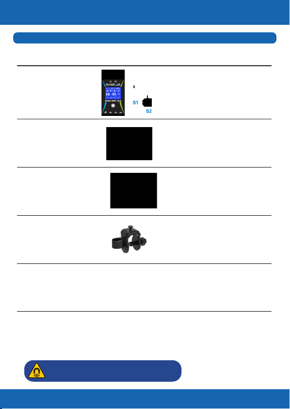
Controller x1
1. Controller with touch
panel & two Dual Sensors
2. Max. Mounting Thickness :
1/2 inch (12.7 mm)
Head : 8.2 feet (250 cm)
DC Pump x3
Universal Power
Adapter x1
Universal Power Supply :
100-240 VAC
A connector to break
the siphon
Siphon Break x3
For rimmed and rimless
aquariums up to 1/2 inch
(12.7 mm)
Universal Tube
Holder x3
Picture
Item
List of Parts (Can Be Purchased Separately)
Tubing 19.6 feet
(600 cm) Used with DC Pumps
Change for Simple
Description
1
Caution:RiskofInjuryfromStrongMagnets

Controller & Dual Sensors
Change for Simple
2
Smart AWC Duo Controller
High Level ATO/AWC Sensor*
High Level Failsafe Sensor
High Level Dual Sensor
Low Level Failsafe Sensor
Low Level AWC Sensor*
Low Level Dual Sensor
*The High Level ATO/AWC Sensor must be at least 1/4 inch
(6 mm) higher than the Low Level AWC Sensor, or Smart AWC
Duo will not work properly.
: High Level Dual Sensor
: Low Level Dual Sensor
: Power DC Jack
: ATO Filling Pump/ Freshwater AWC
Filling Pump Jack
: AWC Drain Pump Jack
: Saltwater AWC Filling Pump Jack

Installation
Change for Simple
3
*Please avoid setting up the sensor in an area with micro bubbles
or direct light.
Step 1 :
Mount the blue sensor
( ) at normal water level S1
– ATO water level (with
the lower sensor
indicating the water
level) on the tank/sump
with the magnet.*
1. AWC
(Auto Water Change)
i. Saltwater Aquarium
Tank/Sump
WaterChangeVolume
AWCDrainPump
WasteWater
WasteWaterContainer Tank/Sump
Step 4 :
Connect AWC
drain pump to
P2.
Step 2 :
Mount the green sensor
( ) at low water level S2
(with the top sensor
indicating the water
level) on the tank/sump
with the magnet.*
Arrow on siphon break
indicates water ow direction.
Air In
Water Out
*Note : Place siphon break inside the tank/sump but above the
water level.
Siphon break allows air in to break the siphon when the Air In :
pump turns off.
Water drops out of the hole are normal when the pump is on. Water Out :
Step 3 :
Connect AWC drain
tube(pump siphon
break* tubing holder).

Change for Simple
4
AWCFillingPump
Power
WasteWater
Tank/Sump
WasteWaterContainer NewWaterReservoir
AWCDrainPump
*Please avoid setting up the sensor in an area with micro bubbles
or direct light.
Step 1 :
Mount the blue sensor
( ) at normal water level S1
– ATO water level (with
the lower sensor
indicating the water
level) on the tank/sump
with the magnet.*
ii. Freshwater Aquarium
For Freshwater aquariums, P3 is not required.
Tank/Sump
WaterChangeVolume
Step 2 :
Mount the green sensor
( ) at low water level S2
(with the top sensor
indicating the water
level) on the tank/sump
with the magnet.*
Step 7 :
Connect power adapter. Step 6 :
Connect AWC lling pump to P3.
Step 5 :
Connect AWC lling
tube ( pump siphon
break tubing holder).

Change for Simple
5
Power
AWCFillingPump
Tank/Sump WasteWaterContainer
AWCDrainPump
AWCFillingPump
NewWaterReservoir Tank/Sump
Step 4 :
Connect AWC lling
pump to P1.
NewWaterReservoir
Step 7 :
Connect power adapter. Step 6 :
Connect AWC drain pump to P2.
Air In
Water Out
*Note : Place siphon break inside the tank/sump but above the
water level.
Siphon break allows air in to break the siphon when the Air In :
pump turns off.
Water drops out of the hole are normal when the pump is on. Water Out :
Arrow on siphon break
indicates water ow direction.
Step 3 :
Connect AWC lling
tube ( pump siphon
break* tubing holder).
Step 5 :
Connect AWC drain
tube ( pump siphon
break* tubing holder).

Change for Simple
6
*Please avoid setting up the sensor in an area with micro bubbles
or direct light.
2. ATO (Auto Top Off)
Step 1 :
Mount the blue sensor
( ) at normal water level S1
(with the lower sensor
indicating the water
level) on the tank/sump
with the magnet.*
Tank/Sump
ATOFillingPump
ATOReservoirTank/Sump
Step 3 :
Connect ATO
lling pump
to P1.
Arrow on siphon break
indicates water ow direction.
Air In
Water Out
*Note : Place siphon break inside the tank/sump but above the
water level.
Siphon break allows air in to break the siphon when the Air In :
pump turns off.
Water drops out of the hole are normal when the pump is on. Water Out :
Step 2 :
Connect ATO lling tube
( pump siphon break*
tubing holder).
In freshwater mode,
ATO operates with pump 1.

Change for Simple
7
ATOFillingPump
ATOReservoir
Step 4 :
Connect power adapter.
Tank/Sump
Power
ACSwitch
Tank/Sump
OpticalLevelSensor
Reservoir
ACFillingPump AC
Power
*The DC pumps can be replaced with larger AC pumps with
AUTOAQUA Smart AC Switch

Calculating the Water Change Volume
Change for Simple
8
The volume can be calculated by multiplying the width and length
of your tank and the distance between the pyramids of the two
sensors.*
For example, a tank is 18 inches in length and 17 inches in width. If
the distance between the two sensors is 3 inches, the water change
volume is approximately 4 gallons.
18” (L) X 17” (W) X 3” (H) = 918 cubic inches (around 4 gallons)**
* The water volume might be inuenced by factors such as the
speed of return pump.
**231 cubic inches = 1 US gallon
Length:18”
Width:17”
WaterChangeVolume Height:3”

*During water change process, pressing can stop the process
and return to the previous AWC MANUAL/AUTO setting page. Also,
ATO is forced to be turned off if its previous status is on and at the
same time the controller gives a ve-second audible and visual alert
( ashing).
Icons & Buttons for Setting
Change for Simple
9
1Turn ATO on or off
1 2 3 4
5
6
2Choose AWC MANUAL / AUTO mode or
turn AWC off
1. Start / pause / resume the AWC process
2. Dismiss alarm
3
Choose the setting item in the AWC MANUAL /
AUTO mode
4
1. Increase day / hour
2. Choose Saltwater / Freshwater mode
5
1. Decrease day / hour
2. Choose Saltwater / Freshwater mode
6
1. Wake up the display
2. Dismiss alarm
3. Resume AWC process
4. Return to AWC setting page*
5. Reset (hold at least for 8 seconds until the
display goes black)
7
No.
7
Este manual sirve para los siguientes modelos
1


