Au3Tech SC1000 Manual de usuario

WUHAN AU3TECH TRADING CO., LTD
1
MCC3721H User’s Quick Setup V1.02
WUHAN AU3TECH TRADING CO., LTD
Email: info@au3tech.com
Web: www.au3tech.com
1. Product Overview
SC1000 is a new generation CNC system software which is specially developed towards fiber
laser cutting field. It has enough external devices and powerful function.
2. Wiring diagram of Motion control card MCC3721H.
The explanations of each port:
ports
function
remark
Power
input
+24V
DC24V input + end
Recommend to use DC
24V/10A power supply
PG
Protective ground
0V
DC input - end,power GND
X/Y Axis’
limit
input
X+
X Axis’ positive limit input,special
signal,low-level propagation is effective.
X Axis’ limit input
X0
X Axis’ origin signal,special signal,low-
level propagation is effective.
X-
X Axis’ negative limit input,special
signal,low-level propagation is effective.
0V
GND, X Axis’ limit signal COM port

WUHAN AU3TECH TRADING CO., LTD
MCC3721H User’s Quick Setup V1.02
2
Y+
Y Axis’ positive limit input ,special
signal,low-level propagation is effective.
Y Axis’ limit input
Y0
Y Axis’ origin signal,special signal,low-
level propagation is effective.
Y-
Y Axis’negative limit input,special
signal,low-level propagation is effective.
0V
GND, Y Axis’ limit signal COM port
Power
output
24A
The 1st DC24V output + end
It can supply standard
TTL for Axis’ limit
switch/general output
port.
24B
The 2nd DC24V output + end
0V
DC24V output GND
X/Y Axis’
controllin
g ports
X
X Axis motor’s controlling signal
DB15 female
Y1
Y1 Axis motor’s controlling signal
DB15 female
Y2
Y2 Axis motor’s controlling signal
If Y Axis is set up as dual -
drive mode, it is Y2 Axis; if
Y Axis is set up as single
drive mode, it is Y1 Axis’
controlling
port( standby ).
General
custom
output
DO1
The 1st general output port
DO2
The 2nd general output port
COM1
General output COM port
DO3
The 3rd general output port
DO4
The 3rd general output port
DO5
The 5th general output port
DO6
The 6th general output port
COM2
General output COM port
DO7
The 7th general output port
DO8
The 8th general output port
Thyristor
output
DO9
The 1st thyristor output port
DC 24V/ 1A
0V
Thyristor output COM port
DO10
The 2nd thyristor output port
PWM
output
P+
PWM signal output + end
PWM TTL: 24V/5, It can
be configured by the
jumper nearby.
p-
PWM signal output - end
Analog
output
AO1+
The 1st analog output port+ end
The voltage of analog
output is between 0V and
10V, which can be
configured by software.
AG
Analog output GND
AO2+
The 2nd analog output port + end
General
custom
input
DI1
The 1st general input port, low-level
propagation is effective(Default).
DI2
The 2nd general input port, low-level
propagation is effective(Default).
DI3
The 3rd general input port, low-level
propagation is effective(Default).
DI4
The 4th general input port, low-level
propagation is effective(Default).

WUHAN AU3TECH TRADING CO., LTD
MCC3721H User’s Quick Setup V1.02
3
DI5
The 5th general input port, low-level
propagation is effective(Default).
DI6
The 6th general input port, low-level
propagation is effective(Default).
DI7
The 7th general input port, low-level
propagation is effective(Default).
DI8
The 8th general input port, low-level
propagation is effective(Default).
0V
Signal input COM port
Ethernet
1X
The 1st industrial Ethernet interface
These two ports can be
arbitrarily configured
2X
The 2nd industrial Ethernet interface
General
serial
port
RS232
DB9, RS232 serial port
It can butt-joint with laser
CON16
Four-pin terminal
The same interface with
DB9 port
FTC
signal
Con5
Four-pin aerospace plug, the FTC’s capacitive
signal interface of Z axis
Connected with amplifier
ZAxis’
controllin
g port
Z AXIS
ZAxis motor’s controlling signal
Z Axis’
limit
input
LL
ZAxis’ negative limit input
UL
ZAxis’ positive limit input
24V+
Powering port for Z axis’ limit sensor
0V
GND, Z Axis’ limit signal COM port
USB
U69
Wireless remoter’s USB interface
3. Installation and wiring of CNC system
3.1 Installation dimension.
SC1000 CNC system supports 35mm’s DIN-Rail Mounting, 315mm (length) x 120mm(wide).

WUHAN AU3TECH TRADING CO., LTD
MCC3721H User’s Quick Setup V1.02
4
3.2 Installation of limit port or other IO port.
Limit input.
SC1000 CNC system software provides three axis’ limit input ports, which are X axis, Y axis, Z axis.
Take X axis as an example, installing axis’ limit signal. NPN photoelectric switch’s typical wiring
shows as below:
General custom output port:
SC1000 CNC system software provides 8 kinds of general custom output ports, and the function of
each output port can be arbitrarily configured by software. The output port is passive output port.
The output mode shows as below:
Thyristor output port:

WUHAN AU3TECH TRADING CO., LTD
MCC3721H User’s Quick Setup V1.02
5
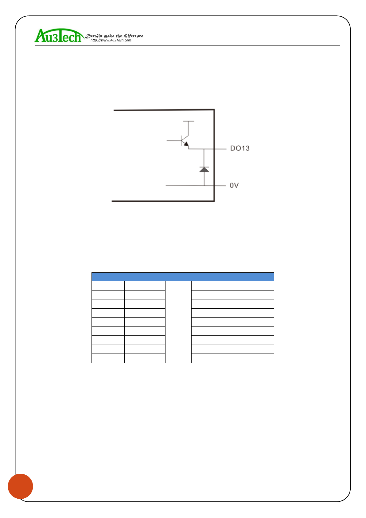
SC1000 CNC system software provides 2 kinds of thyristor output ports, and the function of output
port can be arbitrarily configured by software. The output port is active output port, and the drive
capability in maximum is 24V/1A, which can directly drive 24V DC solenoid valve.
The output mode shows as below:
3.3 Connecting X/Y axis’ servo driver
SC1000 CNC system software provides 4 kinds of servo control interfaces, which are X axis, Y1 axis,
Y2 axis, Z axis. The connecting type is DB15 female. When the system is dual - drive mode, Y1 axis
and Y2 axis separately controls Y axis’ two kinds of servo drivers. And when it’s single drive mode,
Y1 axis controls Y axis’ servo driver. The definition of these four servo control interfaces are the
same, they all adapt the position loop control mode. The definition of each pin shows as below:
Axis’ servo control interface (DB15 female)
Pin
Signal
Pin
Signal
1
PUL+
9
PUL-
2
DIR+
10
DIR-
3
A+
11
A-
4
B+
12
B-
5
Z+
13
Z-
6
SON
14
ALM
7
CLR
15
0V
8
24V
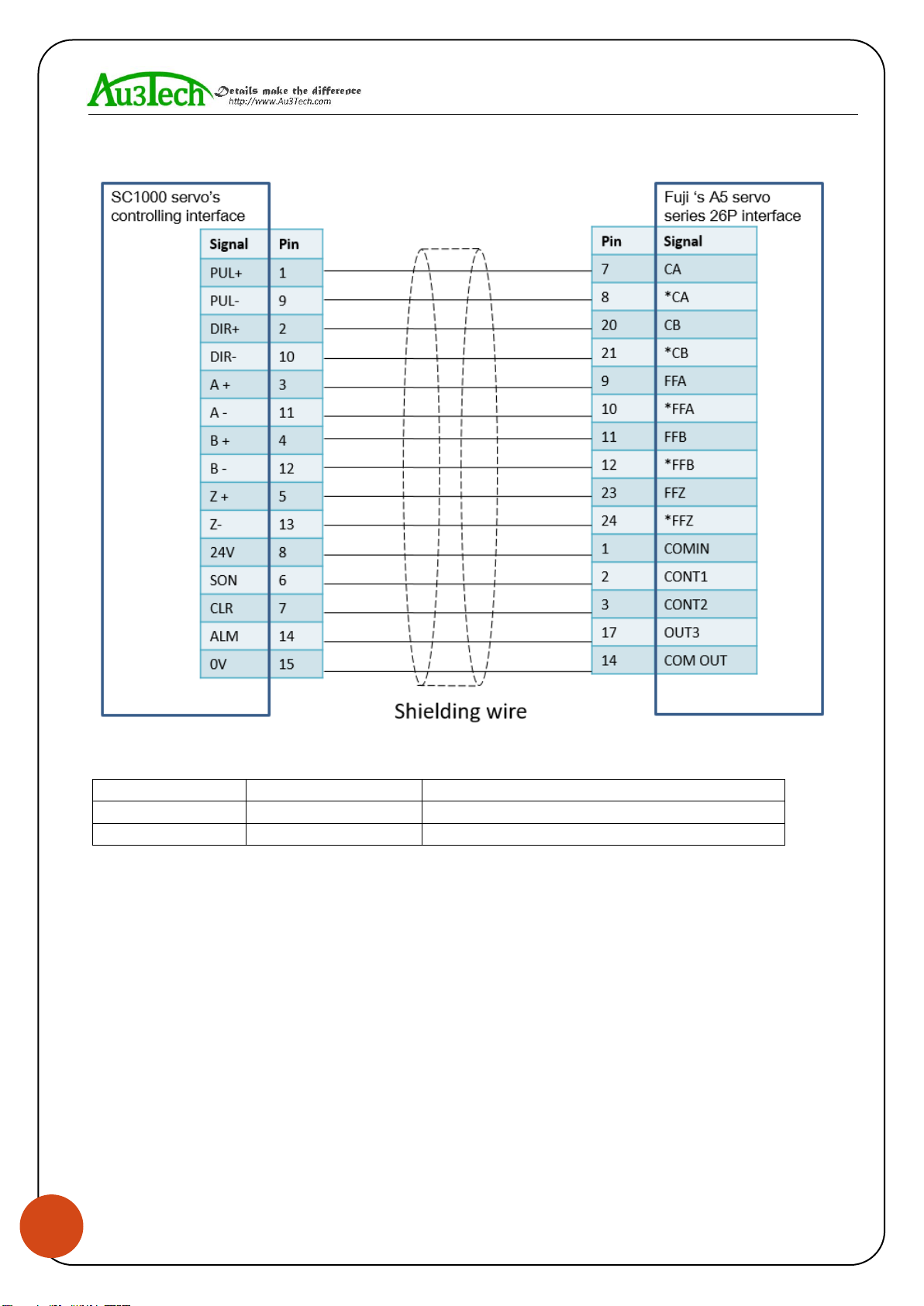
SC1000 CNC system software adapts “pulse + direction signal” to control servo driver, which can
support all kinds of servo driver such as “Yaskawa”、“Panasonic”、“Fuji”、“Delta”、“Kymmene”、
“Adtech”and so on. The wiring mode shows as below:

WUHAN AU3TECH TRADING CO., LTD
MCC3721H User’s Quick Setup V1.02
6
Panasonic’s MINAS-A5 servo series low-speed pulse wiring diagram shows as below.
The basic parameter settings of Panasonic’s A5 servo series shows as below.
Parameter
Set value
Meaning
PR001
0
Set servo control mode as position mode
PR007
3
Set as “Pulse + Direction” mode
PR005
0
Set pulse frequency in maximum

WUHAN AU3TECH TRADING CO., LTD
MCC3721H User’s Quick Setup V1.02
7
Yaskawa’s ∑-V servo series wiring diagram shows as below:
The basic parameter settings of Yaskawa’s ∑-V servo series shows as below.
Parameter
Set value
Meaning
Pn000
001X
Set servo control mode as position mode
Pn00B
default
When it has single-phase power input, set it as 0010
Pn200
2000H
Choose the pulse mode
Pn50A
8100
Clockwise drivable
Pn50B
6548
Un-clockwise drivable

WUHAN AU3TECH TRADING CO., LTD
MCC3721H User’s Quick Setup V1.02
8
Fuji’s A5 servo series wiring diagram shows as below:
The basic parameter settings of Fuji’s A5 servo series shows as below.
Parameter
Set value
Meaning
PA-101
0
Set servo control mode as position mode
PA-103
0
Set as “Pulse + Direction” mode

WUHAN AU3TECH TRADING CO., LTD
MCC3721H User’s Quick Setup V1.02
9
Schneider’s Lexium-23D-CN servo series wiring diagram shows as below:
The basic parameter settings of Schneider’s Lexium-23D-CN servo series
shows as below.
Parameter
Set value
Meaning
P1-00
0002
Choose the pulse mode
P1-01
0000
Position mode
P2-00
Factory default :35
Position controls proportional gain and adjust accordingly.
P2-10
101
Set DI1 port as servo on
P2-14
102
Set DI5 port as alarm clear
P2-15
0000
Set DI6 port as null
P2-16
0000
Set DI7port as null
P2-17
0000
Set DI8 port as null
P2-22
0007
Set DO5 port as servo alarm
P2-68
0001
When L1/L2 and SON are valid at the same time, motor
works. (If not set this parameter, motor can’t work.)

WUHAN AU3TECH TRADING CO., LTD
MCC3721H User’s Quick Setup V1.02
10
Delta ASDA –B2 series wiring diagram shows as below:
The basic parameter settings of Delta ASDA –B2 servo series shows as below.
Parameter
Set value
Meaning
P1-01
0
Position mode
P2-00
Factory default :35
Position controls proportional gain and adjust
accordingly.
P2-10
101
Set DI1 port as servo on, logic is normally open.
P2-14
102
Set DI5 port as alarm clear, logic is normally open.
P2-15
007
Set DI6 port as null
P2-16
007
Set DI7 port as null
P2-17
007
Set DI8 port as null
P2-22
007
Set DO5 port as servo alarm, logic is normally closed.
Otros manuales para SC1000
1
Este manual sirve para los siguientes modelos
1
Tabla de contenidos


